Yamaha rx v657
This is the 48 pages manual for yamaha rx v657.
Read or download the pdf for free. If you want to contribute, please upload pdfs to audioservicemanuals.wetransfer.com.
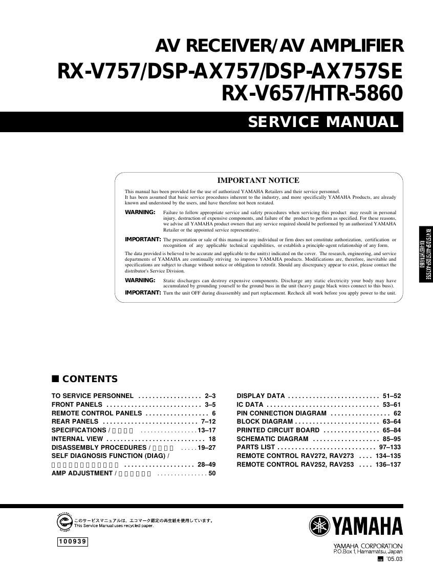
Extracted text from yamaha rx v657 (Ocr-read)
Page 1
AV RECEIVER/AV AMPLIFIER
RX-V757/DSP-AX757/DSP-AX757SE
RX-V657/HTR-5860
SERVICE MAN UAL
i IMPORTANT NOTICE
This manual has been provided for the use of authorized YAMAHA Retailers and their service personnel,
it has been assumed that basic service procedures inherent to the industry. and more specifically YAMAHA Products. are already
known and understood by the users. and have therefore not been restated
WARNING: Failure to follow appropriate servtce and safety procedures when servicing this product iay result in personal
injury. destruction of expensive components. and failure of the product to perform as specified. For these reasons.
we advtse all YAMAHA prodtict owners that any service required should be performed by an authorized YAMAHA
Retailer or the appointed servtce representative.
IMPORTANT: The presentation or sale of this manual to any individual or firm does not constitute authorization. certification or
recognition of any applicable technical capabilities. or establish a principleeagem relationship ofany form.
The data provided is believed to be accurate and applicable to the unit(s) indicated on the cover. The research. engineering, and service
departments of YAMAHA are continually striving to improve YAMAHA products. Modifications are. therefore. inevitable and
specifications are subyeci to change without notice or obligation to retrofit. Should any discrepancy appear to exist. please contact the
dtslnbulots Service Division.
WARNING: Static discharges can destroy expensIVe components. Discharge any static electricity your body may have
accumulated by groundtng yourself to the ground buss in the unit (heavy gauge black wires connect to this busst.
. IMPORTANT: Tum the unit OFF during disassemhly and part replacement. Recheck all work before you apply power to the unit.
I CONTENTS
TOSERVICEPERSONNEL 2-3 DISPLAYDATA..........................51-52
FRONTPANELS...........................3-5 ICDATA................................53-61
REMOTECONTROLPANELS..................6 PINCONNECTIONDIAGRAM 62
REARPANELS 7-12 BLOCKDIAGRAM........................63-64
SPECIFICATIONS/DUDE ................. 13-17 PRINTED CIRCUIT BOARD 65-84
INTERNALVIEW............................18 SCHEMATICDIAGRAM ...................85-95
DISASSEMBLYPROCEDURES/DUDE] ..... 19-27 PARTSLIST............................97-133
SELF DIAGNOSIS FUNCTION (DIAG) / REMOTE CONTROL RAV272, RAV273 . . . . 134-135
DDDDDDDDDDDD ....................28-49 REMOTECONTROLRAV252,RAV253136-137
AMPADJUSTMENT/DDDDDD ............... 50
:09- EX?:J7)II;. I: 7-Oaimiififiéfifi L/Ui'fi.
This Service Manual uses recycled paper.
YAMAHA CORPORATION
POBox l. Hamamatsu. Japan
M 05.03
3.2
5.
E
E
E
is
Page 2
RX-V757/DSP-AX757/DS P-AX757SE
RX-V657/HTR-5860
I SELF DIAGNOSIS FUNCTION (DIAG)/ I] I] I] I] I] III I] [I I] I] I]
This product has a built-in self diagnosis function (DIAG) to D D D D [I] [I [I] D [I] Ll [I L] [I [I [I D [I Ll [I L] [I [I [I D
facilitate inspection. measurement and determination of a
faulty item, ifany.There are 20 DIAG menu items, each hav- D D [I] D D D D [I] D D D D D
ingsubmnunemsl nnnnnnnnnmnnnmnnnnnnnnn
D D D D D D D D D
No. DIAG menu Sub-menu
1 BYPASS 1.ANALOG BYPASS
2. DSP BYPASS
2 RAM THROUGH 1. RAM MARGIN
2. RAM FULL BIT
3 PRO LOGIC 1. PRO LOGIC
4 SPEAKERS SET 1. FRNT : SML OdB
2. CENTER : NONE
3. LFE/B : FRNT
4. Pres Mix : Sch
5. Front GAIN 1
6. Front GAIN 2
7. Zone 2 Amp ON
5 XCH INPUT 1. XCH INPUT76
2. XCH INPUT78
6 MIC CHECK 1, MIC CHK
7 VFD CHECK 1.VFD CHECK (Initial display/I] U I] D )
2. VFD OFF/OSD OFF
3. VFD ALL/OSD 128 character pattern
4. VFD DIMMER/OSD OFF
5. VFD PATTERN/OSD OFF
8 MANUAL TEST 1.TEST ALL
2. TEST FRNT L
3. TEST CENTER
4. TEST FRNT R
5. TEST SURR R
6. TEST SB R
7. TEST SB L
8. TEST SURR L
9. TEST PRES L
10. TEST PRES R
11.TEST LFE
9 FACTORY PRESET 1. PRESET INHI (memory initialization inhibited / I] I] I] I] I] I] I] I] I] I] )
.PRESET RSRV (memory initialized/I] I] I] I] I] I] D D )
10 AD DATA CHECK . DC/FS (protection)
.THM
. IMP SW/POWER LIMIT
. PANEL KEY
11 V CONV STATUS . LOW BYTE
. HIGH BYTE
12 XM STATUS .XMS1 (No applied to these models / I]
|:I|:I
|:l|:l
13 IF STATUS . DST:
.DMD:
.DIF:
.PC:
.CSI:
.CSZ:
2
1
2
3
4
1
2
1 I]
2. XMS2 (No applied to these models / I] I]
1
2
3
4
5
6
7
.DEI:
28