Yamaha rx 530

This is the 34 pages manual for yamaha rx 530.
Read or download the pdf for free. If you want to contribute, please upload pdfs to audioservicemanuals.wetransfer.com.

Page: 1 / 34
yamaha rx 530

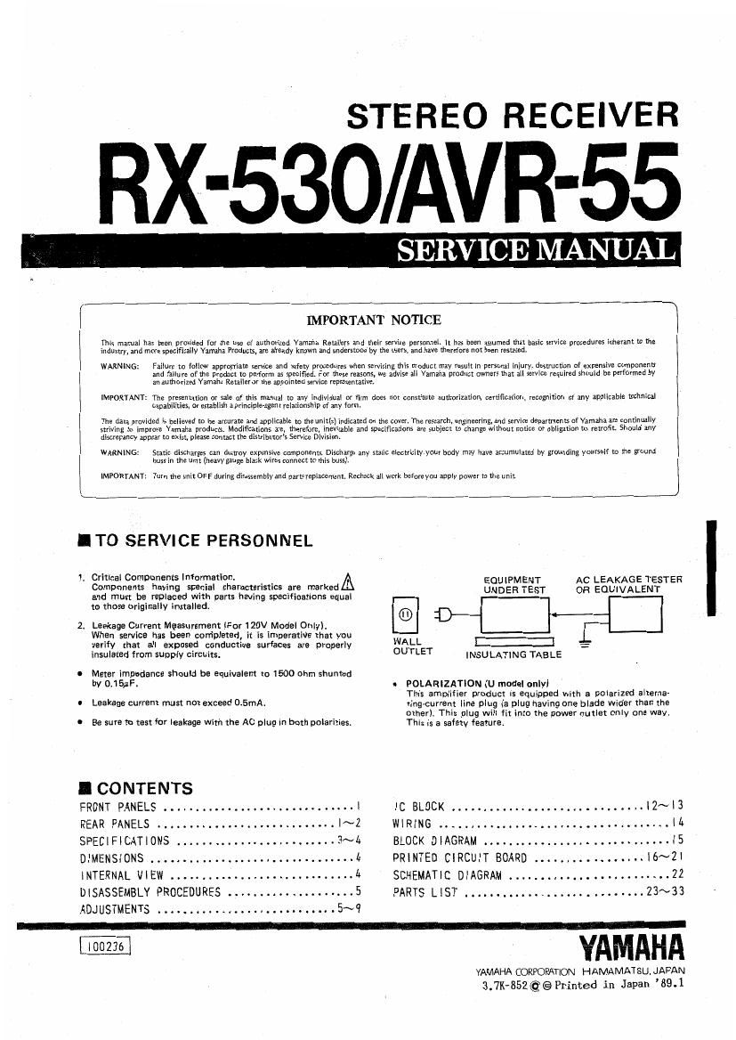
Extracted text from yamaha rx 530 (Ocr-read)


Page 1

STEREO RECEIVER

RX-530/AVR-55

SERVICE MANUAL

r
IMPORTANT NOTICE

This manual has been providad for the use of authorized Valnalla Recall": and their service personnel, It has been assumed that basic srrvlce procedures inhemnt to the
Industry, and more specifically Vamzlli Products, an: already known and understood by the users, and hue {flarefcre not bean rescaudr

WARNING: Failure to follow appropriam service and safny procedurss when servicing th5 product may result in parsonal iniury, destruction of expensive component:
and failure of the product to perform x specified. Fur these reasons, we advis: all Yamaha product owners mat all service vequlrcd should he performed by
an whorized Yamaha Retailer or the appointed service representative,

IMPORTANT: The prcsenutlon or sale of this manual no any Individual or firm does no! constitute authoritarian, unification, recognition of any applicable mchnlcal
Capabilities, or establish a principle-agent ralationship of any form.

The data provided is believed to b: accuram and applicable to me unitlsl lndlcatedon the cum The research, engincering, and service deparancnts orvmaha arc mntinually

striving to improve Yamaha products. Modifications are, therefore, Inimitable and specifications are subircl to Chang: without notice cr obligation to revofit Should any

dismnancy appear to exist, please contact the distributors Service Divisinn,

WARNING: Static discharges can destroy expensive components. [Jimmy any sutic electricityyour body may have accumulated by grounding yourself to me ground
buss in the unit (heavy gaug: black wires connectto this buss).

l
|
IMFORTANT: Turn the um: orr during Aisassembly and parts replaaemenl. Rmheck all work befnrc you apply power [a [he uniL

I TO SERVICE PERSONNEL

1 Critical Components Information. EQUIPMENT AC LEAKAGE TESTER
Components having special characteristics are marked UNDER 1-551- OR EQUIVALENT

and must be replaced with parts having specifications equal

to those originally installed.

2. Leakage Current Measurement (For 120V Model Only).
Whan service has been completed it is Imperativa that you
verify that all exposed conductive surfaces are properly WALL :3 _
insulated from supply circuits. OUTLET INSULATING TABLE
0 Meter impedance should be equivalent to 1500 ohm shunted
by 0.15uFt o POLARIZATION (U model onlyl
This amplifier product is equipped with a polarized alterna»
I Leakage current must not exceed 0.5mA. tingAcurrent Ilne plug (a plug having one blade wider than the
otherl This plug will fit into the power outlet Only one way.
I Be sure to test for leakage with the AC plug in both polarities. This is a safety featuret

ICONTENTS

FRONT PANELS l IC BLOCK l2~l3
REAR PANELS |~2 WIRING IA
SPECIFICATIONS 3~4 BLOCK DIAGRAM I5
DIMENSIONS 1. PRINTED CIRCUIT BOARD ...............V.lé~21
INTERNAL VIEW 4 SCHEMATIC DIAGRAM 22
DISASSEMBLY PROCEDURES 5 PARTS LIST 23~33
ADJUSTMENTS . . ...........5~9

BB . YAMAHA

YAMAHA CORPORATION HAMAMATSU. JAPAN
3.7K-852@ @ Printed in Japan 89.1