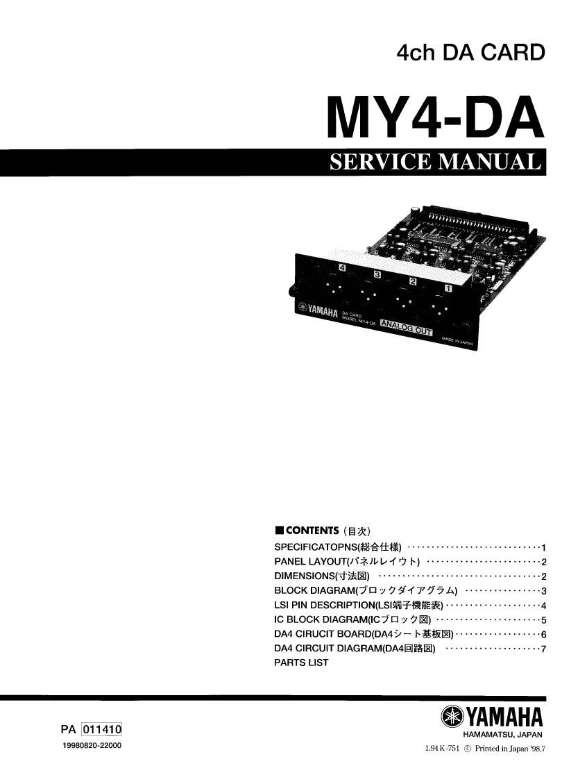
Yamaha my4 da service manual
This is the 14 pages manual for yamaha my4 da service manual.
Read or download the pdf for free. If you want to contribute, please upload pdfs to audioservicemanuals.wetransfer.com.
Extracted text from yamaha my4 da service manual (Ocr-read)
Page 2
MY4-DA
IMPORTANT NOTICE
This manual has been provided for the use of authoriled Yamaha Retallers and their service personnel. It has been assumed that
basic ervice procedures inherent to the industry, and specifically Yamaha Products, are already known and understood by the
users and have therefore not been restated.
WARNING: Failure to follow appropriate service and safety procedures when servicing this product may result in per
sonai injury, destruction of expensive components and failure of the product to perform as specified. For
these reasons, we advice all Yamaha product owners that all service required should be performed by an
authorized Yamaha Retailer or the appointed service representative.
IMPORTANT: Thls presentation or sale of lhls manual to any individual or firm does not constitute authorllalion, cenl'lr
Datiofn, recognilion of any applicable Iechnical capabilities, or establish a principalragent relationship of
any firm.
The data provided id pelived to be accurate and applicable to the unittsl indicated on the cover. The research engineering, and
Service departments of Yamaha are continually striving to improve Yamaha products.Modlflcatiuns are, thereiore, inevitable
and changes In specification are subject to change without notice or obligation to retrofit. Should are discrepancy appear to
exist. please contectthe distributors Service Division.
WARNING: Stat": dlscliarges can destroy expensive components. Discharge any slalic electricity tau body may have
accumulated by grounding yourself to the ground buss in the unit (heavy gauge black wires connect to
this buss.)
IMPORTANT: Turn the unit on: during disassernoty and parts replacement. Recheck all work belure you apply power
to the unit.
WARNING: CHEMICAL CONTENT NOTICE!
The soider used in the production of this product contains LEAD. In addition, other electrical/electronic anmr plastic (where
applicable) components may also contain traces of chemicals iound py the California Health and Weifare Agency (and possibly
other entities) to cause cancer and/or binh defects or other reproductive harm.
30 NOT PLACE SOLDER, ELECTICAL/ELECTRONIC 0R PLASTIC COMPONENTS lN YOUR MOUTH FOR ANY REASON WHAT
O EVERI
Avoid prolonged, unprotected contact between soider and your skini When soldering, do not inhale solder fumes or expose
eyes to solder/flux vaport
If you come in contact with solder or components located inside the enclosure of this product, wash your hands before handing
food.
.SPECIFICATIONS (fifiiflifi)
Total Harmonic Less than 0.1% ZOHZ to 20kHz @+4dB into 6000
Distortion Less than 0.02% lkHz @+18dB into 600 0
Dynamic Range 110dB typ. DA Converter @Gain SW: +4dB
(maximum level to noise level)
Hum & Noise *1 ~94dB residual output noise @Gain SW: +4dB, OUTPUT off
DA converter 20bit linear, 8 times oversampling
Frequency Response +1, >3dB 20Hz - ZOkHz @+4dB into 6000, Gain SW: +4dB
*1: Hum & Noise are measured with a GdB/ octave filter @12.7kHz; equivalent to a 20kHz filter
with infinite dB/ octave attenuation.
Output GAIN Actual Source For Use With OlltPllt LEVCI Connector
Terminals SWitCh Impedance Nominal Normal Max. before clip
ANALOG +18dB . +4dB (1.23V) * +18dB(6.16V) * XLR-332 type
150 O 600 Q Li
OUT 1-4 +4dBV es -10dBv(316mV)** +4dBV(1.58V) ** a3alanced ***
* OdB is referenced to 0.775 Vrms.
** 0dB is referenced to 1.00 Vrms.
*** ANALOG OUT 1-4 XLR type connectores are balanced. (1=GND, 2=HOT, 3=COLD)
PARAMETER CONDITIONS MIN I'Yl MAX UNII
Sampling Frequency huge 30.08 5088 kHz
Power Requirements DC digital SV 80 mA
DC analog 5V 20 mA
DC analog -5V 110 mA
DC analog +15V 80 mA
DC analog r15V 90 mA
Temperature Range Operating 10 35 C
Storage -20 55 C
Demensions Panel Vindth 120 mm
Height 40 mm
Board Width 100 mm
Depth 160 mm
Net weight 210 g