Yamaha m 40

This is the 16 pages manual for yamaha m 40.
Read or download the pdf for free. If you want to contribute, please upload pdfs to audioservicemanuals.wetransfer.com.

Page: 1 / 16
yamaha m 40

Extracted text from yamaha m 40 (Ocr-read)


Page 1

438

STEREO POWER AMP
.- .MICH
AUDIO-ELEKTlggNliEgéKfiExglEEB

KORTESTH lo. TEL/FAX 694 41 54

M-40

SERVICE MANUAL

mum sat-1» m suntan-Owen mm: M40

_«...»i_

we:

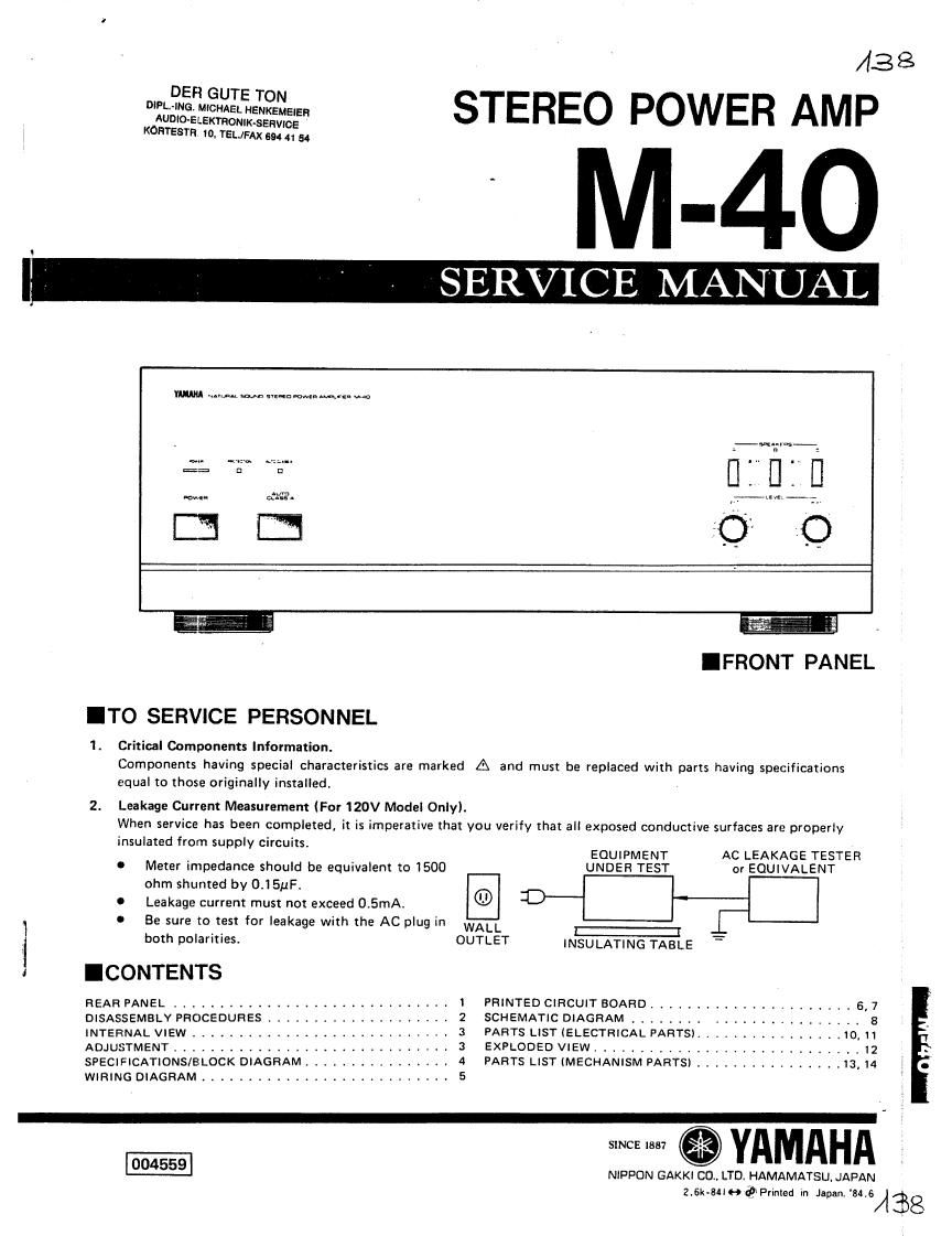
IFRONT PANEL

ITO SERVICE PERSONNEL

1. Critical Components Information.
Components having special characteristics are marked A and must be replaced with parts having specifications
equal to those originally installed.

2. Leakage Current Measurement (For 120V Model Only).

When service has been completed, it is imperative that you verify that all exposed conductive surfaces are properly
insulated from supply circuitsl

EQUIPMENT AC LEAKAGE TESTER
0 Meter impedance should be equivalent to 1500 UNDER TEST or EQUIVALENT
ohm shunted by 0.151.1F.
I Leakage current must not exceed 0.5mA. ® C
.1 0 Be sure (arrest for leakage with the AC plug in WALL E: -
i both polarities. OUTLET INSULATING TABLE
I ICONTENTS
REAR PANEL ................ I PRINTED CIRCUIT BOARD ...................... 6, 7
DISASSEMBLY PROCEDURES ...... 2 SCHEMATIC DIAGRAM ........ y _ I 8
INTERNAL VIEW .............. . . . . . 3 PARTS LIST (ELECTRICAL PARTS). . .10, 11
ADJUSTMENT .............................. 3 EXPLODED VIEW ............ , , . . . , . . 12
SPECIFICATIONS/BLOCK DIAGRAM ................ 4 PARTS LIST (MECHANISM PARTS) ................ 13,14
WIRING DIAGRAM ........................... 5
- NIPPON GAKKI CD. LTD. HAMAMATSU. JAPAN

2.6k.sue@Pvimed in Japan. mus/138

Page 2

IDISASSEMBLY PROCEDURES

M-4-0

Step hem Work
1 Top Cover 1. Remove 4 screws (D .
2. Remove 2 screws ®
2 Front Panel Remove 5 screws ©.
:3 Bottom Cover Remove screws @.
4 Main Circuit Board with Heat Sinks 1. Remove 4 screws (53 .
2. Remove 6 screws @
3, Remove 2 screws (3 .
5 Rear Panel Remove 12 screws . .

From Panel