Yamaha dvd s795
This is the 90 pages manual for yamaha dvd s795.
Read or download the pdf for free. If you want to contribute, please upload pdfs to audioservicemanuals.wetransfer.com.
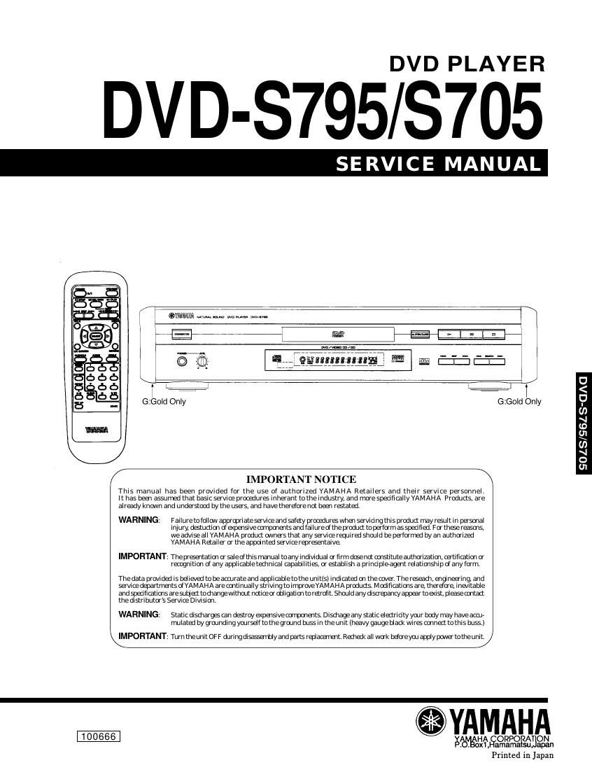
Extracted text from yamaha dvd s795 (Ocr-read)
Page 1
DVD PLAYER
DVD-S795/S705
SE RVICE MANUAL
n "me i
I A l
i
sis iEJ-I/
G:Gold Only G:Gold Only
D
<
9
(I)
si
1.0
fl
(0
s1
0
01
IMPORTANT NOTICE
This manual has been provided for the use of authorized YAMAHA Retailers and their serVice personnel.
It has been assumed that basic service procedurs lnherant to the industry, and more spedflcallyYAMAHA Products, are
alrady known and understood by the users, and havetherdore not been ratated.
WARNING: Failure tofollow appropriateserviceand safety prooedura when sevidng this product may rsult in personal
injury, datuctlon of apewsivecompments and failure cf theproduct to perform as speofied. For thse reasons,
we adviseall YAMAHA product dimes that any servicerequired should bepe'formed by an authorized
YAMAHA Retailer or the appo nted service repraentaive
IMPORTANT: Theprfientation or salecfthls manual toany individual or firm dose no: mistltuteauthorizatim, certifimtim or
recognition d any applicabletechnial apabilitifi, or stablish a prinopleagent relationship If any form.
The data provided is believed to be accurate and applicable tothe unlt(s) indicatal on the Dover. The raeach, engineering, and
service departme'its dYAMAHA are continually strlvl ng to improveYAMAHA products. M odifiatlons are therefore inevitable
and specifiatims aresutze: toohangewithout nozioeor old igatim to retrcflt. Should any disoanncy appar toe
WARNING: Static disdiargs an dstroy expensive oomponents. Disdiage any static elemrioty your body may have an»
mulated by grounding yourself tothe ground buss in the unit (heavy gauge blad< wirS conned tothis buss.)
IMPORTANT: Turn theunit OF F duringdisaserbly and parts replacement. Redneck all work befoeyou apply poNe totheunit.
.YAMAHA
1 00666 WAEORPOFABON
amamasu
Printed 1n Japan
Page 2
l0
0
[x
Q
lo
01
[x
4
D
>
D
CONTENTS
SPECIFICATIONS ...................................................................... 1-1
LOCALE MANAGEMENT INFORMATION 1-1
TO SERVICE PERSONNEL ................. -2
PREVENTION OF ESD TO ES DEVICES 1-3
PRECAUTION OF LASER DIODE ............................ 1-4
HANDILNG PRECAUTIONS FOR TRAVERSE DECK. 1-4
REAR PANELS .......................................................... -5
OPTICAL PICKUP SELF-DIAGNOSIS AND REPLACEMENT PROCEDURE 1-6
SELF-DIAGNOSIS FUNCTION AND SERVICE MODE -7
SERVICE PRECAUTIONS ........................................ -9
SERVICE TOOLS AND EQUIPMENT 1-9
OPERATING INSTRUCTIONS .......... -1O
ASSEMBLING AND DISASSEMBLING THE CASING AND CHECKING
C. B. A.s
. Disassembly Procedure
. Casing Parts and C.B.A. Pos ons
. Service Positions .................
. Disassembling the Top Cove
. Disassembling the Tray .....
. Disassembling the Front Panel ......
. Disassembling the Loading Base UnIt
. Checking the Module C.B.A. ..............
9. Disassembling the Rear Panel
10. Checking the Power Supply C.B.A.
11. Checking the Mother C.B.A.
12. Checking the Power Switch C.B.A.
13. Checking the Front Switch CB.
14. Checking the Headphone C.B.A.
ooxrmmawm-A
ASSEMBLING AND DISASSEMBLING THE OPTICAL PICKUP
1. Handling the Optical Pickup.
2. Disassembly Procedure
3. Lubricating the Loading Base Uni
4. Static Electricity Countermeasures
5
6
. Disassembling the Clamp Base Uni ..
. Disassembling the Clamp Weight, Clamper Yoke,
Magnet and Clamper ...............
7. Disassembling the Traverse Unit
8. Disassembling the Stepping Motor Unit
9. Disassembling the Optical Pickup Unit .
10. Disassembling the Nut Unit ................
11. Disassembling the Sub-Shaft Preload Spring
12. Assembling the Optical Pickup ......
13. Disassembling the Spindle Motor Unit
14. Optical Pickup Tilt Adiustment ............
15. Disassembling the Intermediate Chassl
16. Disassembling the Vertical Cam and Drive Gear
17. Disassembling the Pulley Gear and Deceleration Gear
18. Disassembling the Mechanism Loading C.B.A.
19. Lubricating the Optical Pickup and Peripheral parts
ELECTRICAL ADJUSTMENT
1. Video Output (Luminance Signal) Adjustment ................... 2-17
2. Video Output (Chrominance Signal) Adjustment
3. Video Component Signal (CB) Output Adjustment
SECTION 3
ABBREVIATIONS ....................................................................... 3-1
BLOCK DIAGRAM
1. OVERRALL BLOCK DIAGRAM ........................................... 3-3
2. SERVOBLOCK DIAGRAM .. .3-5
3. VIDEO BLOCK DIAGRAM .3-7
4. AUDIO BLOCK DIAGRAM .. .3-9
SCHEMATIC DIAGRAM
1. POWER SUPPLY SCHEMATIC DIAGRAM (FOR U, C MODELS) 3-11
. POWER SUPPLY SCHEMATIC DIAGRAM (FOR B, G,A MODELS) 3-13
.ADSC (MODULE C.B.A.1/8)SCHEMATIC DIAGRAM ..... 3-15
. SERVO (MODULE C.B.A. 2/8) SCHEMATIC DIAGRAM 3-17
. AV DECODER (MODULE C.B.A. 3/8) SCHEMATIC DIAGRAM 3-19
.VDAC (MODULE C.B.A. 4/8) SCHEMATIC DIAGRAM 3-21
.FEP (MODULE C.B.A. 5/8) SCHEMATIC DIAGRAM .. 3-23
. CPU (MODULE C.B.A. 6/8) SCHEMATIC DIAGRAM ........ 3-25
9. CLOCK (MODULE C.B.A. 7/8) SCHEMATIC DIAGRAM. 3-27
10. ODC (MODULE C.B.A. 8/8) SCHEMATIC DIAGRAM . 3-29
11. VIDEO (MODULE C.B.A. 1/5) SCHEMATIC DIAGRAM 3-31
12. ADAC C (MODULE C.B.A. 2/5) SCHEMATIC DIAGRAM. 3-33
13. AUDIO AC-3 (MODULE C.B.A. 3/5) SCHEMATIC DIAGRAM 3-35
14. AUDIO OUT (MODULE C. .A. 4/5) SCHEMATIC DIAGRAM .. 3-37
15. OPERATION (MODULE C.B.A. 5/5) SCHEMATIC DIAGRAM 3-39
16. VIDEO COMP SCHEMATIC DIAGRAM (FOR U, C MODELS). 3-41
17. SCART SCHEMATIC DIAGRAM (FOR B, G MODELS . 3-43
18. FRONT SW/HEAD PHONE/POWER SW SCHEMATIC DIAGRAM 3-45
common-pooh)
CIRCUIT BOARD DIAGRAM
1. POWER SUPPLY C.B.A. (FOR U, C MODELS) 3-47
2. POWER SUPPLY C.B.A. (FOR B, G, A MODELS) 3-49
3. MODULE C.B.A. 3-51
4. MOTHER C.B.A. ......................................... 3-55
5. FRONT SW/HEAD PHONE/POWER SW C.B.A 3-57
6. SCART C.B.A. (FOR B, G MODELS). ........ 3-59
7. VIDEO COMP C.B.A. (FOR U, C MODELS) ..................... 3-61
SECTION 4
EXPLODED VIEWS & REPLACEMENT PARTS LIST
1. ELECTRICAL REPLACEMENT PARTS LIST.
2. Casing Parts & Mechanism Section ............
3. Loading Mechanism Section
4. Traverse Section ..............
5. REMOTE CONTROLTRANSMITTER.