Western electric 448 b brochure

This is the 4 pages manual for western electric 448 b brochure.
Read or download the pdf for free. If you want to contribute, please upload pdfs to audioservicemanuals.wetransfer.com.

Page: 1 / 4
western electric 448 b brochure

Extracted text from western electric 448 b brochure (Ocr-read)


Page 1

BELL SYSTEM PRACTICES AB46.448A,B & 454A
Transmission Engineering Data ISSUE 1. SeDtember 1961
Electron Tube Data A T.& T. Co., Standard

ELECTRON TUBE DATA SHEET
WESTERN ELECTRIC 448A,4483,454A ELECTRON TUBE

DESCRIPTION

The 448A, 4483 and 454A electron tubes are high figure of merit tetrodes of the
indirectly heated cathode type. They have plate characteristics approaching those of
a pentode and were designed primarily for use in the TH Radio Relay System.

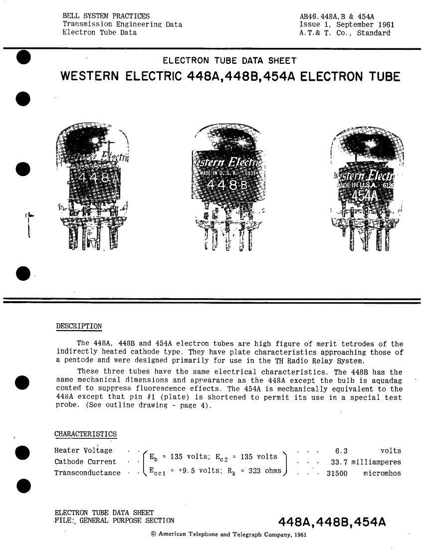
These three tubes have the same electrical characteristics. The 4483 has the
same mechanical dimensions and appearance as the 448A except the bulb is aquadag
coated to suppress fluorescence effects. The 454A is mechanically equivalent to the
448A except that pin #1 (plate) is shortened to permit its use in a special test
probe. (See outline drawing - page 4L

CHARACTERISTICS

Heater Voltage ~ - E 135 olt E 135 volts - . . 6.3 volts
= V S; .= . .

Cathode Current - b CZ ] - - - 33.7 milliamperes

Transconductance Ecol : +9'5 volts; Rk : 323 ohms 31500 micromhos

ELECTRON TUBE DATA SHEET

FILE; GENERAL PURPOSE SECTION 448A4483'454A

© American Telephone and Telegraph Company, 1961

Page 2

448A,44BB,454A - PAGE 2

GENERAL CHARACTERISTICS

Electrical Data

Heater Voltage - - - - - - - - - - A - A - - - - A - - 6.3 volts
Heater Current - . A . - - - 450 milliamperes
Direct Interelectrode Capacitances (without external shield)
Grid to Plate A - - . A . A - - - 0.03 if
Input: 5; to (h ' k - 512* i. s.) - - - A A - - A , - - 15.4 Luf
Output: p to (h * k - g2 * i. s.) A - A A . - ~ - A - - 2.03 not

Mechanical Data

Cathode A . . . . . . . . . A . . . . A . . . A . . Coated Unipotential
Base A - - A - . - - . . - . . . . . . , See outline drawing Page 4
Mounting Position - . . . Any

Dimensions and pin connections shown in outline drawing on Page 4

Maximum Ratings, Absolute System

Plate Voltage. . . . . A . . . . . . . . . A . . . A . 150 volts
Screen Grid Voltage - - - . - A A A . . A . . A A A . . 150 volts
Control Grid Voltage- A A . A . A A - A A . . A A A A A -50 volts
Plate Dissipation . . A . . A . . . . . A . A A A A A A 6.0 watts
Screen Grid Dissination-- - - - - ~ - . - . A ~ A - A - . 1.75 watts
Control Grid Dissipation A . - . . A - A A . A - - A A . See Footnote *
Cathode Current- A A - . . A - , A . A A . A - A A A 50 milliamperes
Heater - Cathode Voltage - . A A - - A A A . A A A A A . 50 volts
Bulb Temperature A A . A A - . - A A . A A - A A A A - 130' centigrade
Maximum Grid Circuit Resistance for:

Fixed Bias - - 0.05 megohm

Cathode Bias 0.10 megohm

" Operation with the control grid positive with respect to the cathode is not
recommended.