Western electric 442 a brochure

This is the 6 pages manual for western electric 442 a brochure.
Read or download the pdf for free. If you want to contribute, please upload pdfs to audioservicemanuals.wetransfer.com.

Page: 1 / 6
western electric 442 a brochure

Extracted text from western electric 442 a brochure (Ocr-read)


Page 1

BELL SYSTEM PRACTICES SECTION AB46.442A
Transmission Engineering and Data Issue 1, March 1962
Electron Tube Data A.T.& T.Co. Standard

I T II I

ELECTRON TUBE DATA SHEET
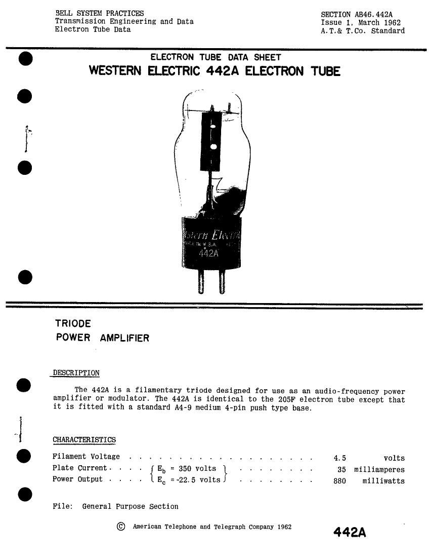
WESTERN ELECTRIC 442A ELECTRON TUBE

. .M~

TRIODE
POWER AMPLIFIER

DESCRIPTION

The 442A is a filamentary triode designed for use as an audio-frequency power
amplifier or modulator. The 442A is identical to the 205F electron tube except that
it is fitted with a standard A4-9 medium 4-pin push type base.

CHARACTERISTICS

Filament Voltage . . . . . . . . , . . . . . . . 4.5 volts
Plate Current. - - . { Eb = 350 volts } . . . . . . . . 35 milliamperes
Power Output Ec =-22.5 volts 880 milliwatts

File: General Purpose Section

© American Telephone and Telegraph Company 1962 442A

Page 2

442A- PAGEZ

GENERAL CHARACTERISTICS

Electrical Data

Filament Voltage (A-C) or (D-C) 4.5 volts
Filament Current . 1.6 amperes
Direct Interelectrode Capacitances

Grid To Plate 5.9 uuf
Input 4.1 uuf
Output 2.2 uuf
Mechanical Data

Cathode . . . . . . . . . . . . . . . . . . . . . . . Coated Filament
Bulb . . . . . . . . . . . . . . . . . . . . . . . . ST 14
Base . . . . . . . . . . . . . . A4- -9 medium 4- -pin
Mounting Position . . . . . . . . . . Preferably vertical; if horizontal, pins

#1 and #2 must lie in same vertical plane
Dimensions and pin connections shown in outline drawing on page 6.

MAXIMUM RATINGS, Absolute System

Plate Voltage . . , . , , , . , . . , . . , , , _ , , 400 volts
Plate Current . . . . . . . . . . . . . . . . . . . . 55 milliamperes
Plate Dissipation , , , . , , . , , , , , , , , , , , , 14 watts

TYPICAL OPERATING CONDITIONS AND CHARACTERISTICS

Filament Voltage (A-C) . . . . . . . . . 4.5 4.5 4.5 4.5 volts
Plate Voltage - - . - . ~ . . - ~ - . 250 300 350 350 volts
Grid Voltage - . - - - - ~ . - . -22 -18 .225 -22.5 volts
Peak A- F Signal Voltage - - - . - . ~ . 22 18 22.5 22.5 volts
Zero Signal Plate Current - - - . - - - - 11.5 30 35 35 milliamperes
Maximum Signal Plate Current. . - - . - - 12 30.5 36 36 milliamperes
Transconductance . - . - . - . - . . - 1350 1880 1950 1950 micromhog
Plate Resistance - - - - - - - - . - . 5300 3800 3700 3700 ohms
Load Resistance ~ - - - - - . - . - ~ 12000 8000 4000 8000 ohms
Amplification Factor - - - . - - - - - ~ 7.2 7.2 7.2 7.2

Maximum Signal Power Output . . - - - - - 550 450 880 760 milliwatts
Total Harmonic Distortion- - - . - - - 4.6 1.6 2.8 1.4 per cent

' If filament is operated on D-C the characteristics will be approximately the same if the grid
voltage, measured from the negative filament, is decreased by 2.3 volts.

\

h...