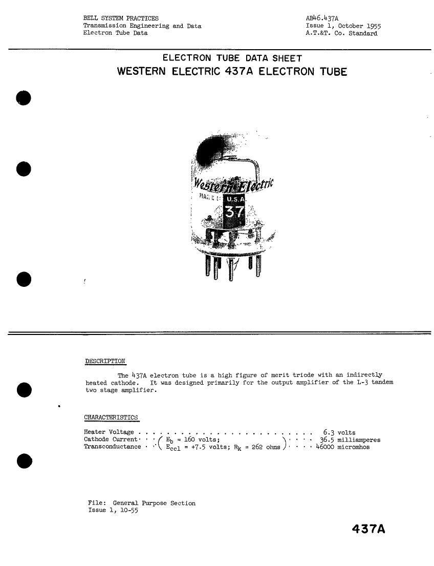
Western electric 437 a brochure
This is the 4 pages manual for western electric 437 a brochure.
Read or download the pdf for free. If you want to contribute, please upload pdfs to audioservicemanuals.wetransfer.com.
Extracted text from western electric 437 a brochure (Ocr-read)
Page 1
BELL SYSTEM PRACTICES AB1+6J+37A
Transmission Engineering and Data Issue 1; October 1955
Electron Tube Data A.T.&T. Co. Standard
ELECTRON TUBE DATA SHEET
WESTERN ELECTRIC 437A ELECTRON TUBE
DESCRIPTION
The h37A electron tube is a high figure of merit triode with an indirectly
heated cathode. It was designed primarily for the output amplifier of the L-3 tandem
two stage amplifier.
CHARACTERISTICS
Heater Voltage . 6.3 volts
Cathode Current' - ' Eb = 160 volts; > ~ - . 36.5 milliamperes
Transconductance - " Eccl = +7.5 volts; RR = 262 ohms - ' M6000 micromhos
File: General Purpose Section
Issue 1, 10-55
437A
Page 2
h37A - Page 2
GEKERAL CHARACTERISTICS
ELECTRICAL DATA
Heater Voltage . . . . . . . . . . . . . . . . . . . . . . . .
6.3 volts
#50 milliamperes
Heater Current . . . . . . . . . . . . . . . . . . . . . . . .
Direct Interelectrode Cepacitances Without kith External
External Shield
Shield §RETlA $3022
Grid to Plate (maximuz) . . . . . . 3.8 3.8 uuf
Inpu ' g to (h+k+i.s.) . . . . . . 11.1 11.3 uuf
DutpLC: p to (h+k+i.s.) . . . . . . 1.0 2.1 uuf
lLtHAHICAL DATA
Cathode . . . . . . . . . . . . . .». . . . . . . . Coated Unipotential
Bulb . . . . . . . . . . . . . . . . . . . . . . . T9
Base . . . . . . . . . . . . . . . . . . . . . . . See outline drawing page h
Haunting Position . . . . . . . . . . . . . . . . . Any
Dinensions and pin connections shown in outline drawing on page L
MAXIMUM RATINGS, Design Center Values
Plate Voltage . . . . . . . . . . . . . . . . . . . . . . . . . 250 volts
Plate Dissipation . . . . . . . . . . . . . . . . . . . . . . . 7.0 watts
Control Grid Dissipation . . . . . . . . . . . . . . . . . . . see footnote 1
Cathode Current . . . . . . . . . . . . . . . . . . . . . . . . L5 milliampeves
Heater-Cathode Voltage . . . . . . . . . . . . . . . . . . . . 50 volts
Bulb Temperature . . . . . . . . . . . . . . . . . . . . . . . 130 centigrade
MAXIMUM CIRCUIT VALUES
Grid Circuit Resistance:
For Fixed Bias . . . . . . . . . . . . . . . . . . . . . . . 0.05 negohm
For Cathode Bias . . . . . . . . . . . . . . . . . . . . . . 0.10 megohm
TYPICAL OPERATING CONDITIONS AND CHARACTERISTICS
PlateVoltage.................. no 160 160volts
Control Grid Voltage . . . . . . . . . . . . . . -2.0 -3.0 --- volts
Control Grid Supply Voltage2 . . . . . . . . . . - --- +7.5 volts
Cathode Bias Resistor2 . . . . . . . . . . . . . --- --- 262 ohms
Plate Current . . . . . . . . . . . . . . . . . . 29.0 25.0 36.5 milliamperes
Amplification Factor . . . . . . . . . . . . . . 1.1.0 h1.0 1+1.o
Plate Resistance . . . . . . . . . . . . . . . . 950 950 900 ohms
Transconductance . . . . . . . . . . . . . . . . A3060 hQOOO 46000 micronhos
Control Grid Voltage (approximate) for
Plate Current of 10 microamperes . . . . . . . -S.0 -6.3 - volts
Modulation
SecondOrder(2FR3.............. - --- -37 db
ThirdOrder(3F)............... --- --- -56db
Load Resistance . . . . . . . . . . . . . . . --- --- 270 ohms
Note 1: Operation with the control grid positive with respect to cathode is not
recommended.
Esta 2: Reference point for Control Grid Voltage is the negative end of the cathode
bias resistor.
Note 3: Ratio of product to fundamental at output for 0.1 volt rms signal from grid
to cathode.
Note #2 Ratio of product to fundamental at output for a 0.2 volt rms signal from
grid to cathode.