Western electric 435 a brochure

This is the 4 pages manual for western electric 435 a brochure.
Read or download the pdf for free. If you want to contribute, please upload pdfs to audioservicemanuals.wetransfer.com.

Page: 1 / 4
western electric 435 a brochure

Extracted text from western electric 435 a brochure (Ocr-read)


Page 1

BELL SYSTEM PRACTICES SECTION ABA6.L35A
Transmission Engineering and Data Issue 2, June 195A
Electron Tube Data A.T.& T.Co. Standard

ELECTRON TUBE DATA SHEET
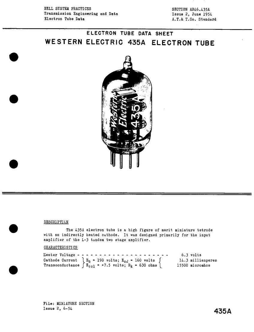
WESTERN ELECTRIC 435A ELECTRON TUBE

DESCRIPTION

The L35A electron tube is a high figure of merit miniature tetrode
with an indirectly heated cathode. It was designed primarily for the input
amplifier of the L-B tandem two stage amplifier.

CHARACTERISTICS

Heater Voltage --------------------- 6.3 volts
Cathode Current Eb - 190 volts; Ecz - 160 volts 1L.3 milliamperes
Transconductance Ecol - +7.5 volts; Rk - 630 ohms 15500 micromhos

File: MINlATURE SECTION

Issue 2, 6-51; 435A

Page 2

L35A - Page 2

GENERAL CHARACTERISTICS
ELECTRICAL DATA

Heater Voltage --------------- ~ - - - - 6.3 volts
Heater Current -------------------- 300 millianperes
Direct Interelectrode Capacitances Without With External
External Shie d
§hjeld (RETEA i315)
Grid to Plate (maximum) ----------- .035 .030 uuf
Input -------------------- 7.9 8.1 uuf
Output ----------- ~ ------- 2.9 3.3 uuf
HECHANICAL DATA
Cathode ----------------------- Coated Unipotentisl
Bulb ------------------------ T6 1/2
Base ------------------------ Small Button 9 Pin
Mounting Position ------------------ Any

Dimensions and pin connections shown in outline drawing on page L

MsiIMUM RATINGS, Design Center Values

Plate Voltage- - -------------------- 19° V°1t5
Screen Grid Voltage ------ - ----------- - 160 volts

Plate Dissipation ------ ~ - - ---------- 3.0 watts
Screen Grid Dissipation ----------------- 0-75 watt
Control Grid Dissipation - - ~ ------------ See footnote
Cathode Current ------- - -------- ~ - - 36 mnliamPSTEB
Heater-Cathode Voltage ----------------- 50 volts

Bulb Temperature ------------------ - - 130 centigrade
Haximum Grid Circuit Resistance for

Fixed Bias - - -------------------- 0-05 mesohm

Cathode Bias - - - . ------------ . ~ - - - 0»10 masohm
TYPICAL OPERATING CONDITILKS AND CHARACTERISTICS

Plate Voltage ------------ 130 160 190 volts
Screen Grid Voltage --------- 130 160 160 volts
Control Grid Voltage1 --------- -l.0 -l.5 97.5 volts
Cathode Bias Resistor -------- --- --- 530 ohms
Plate Current ------------ 10.3 11.6 11.5 milliamperee
Screen Grid Current --------- 3.8 L.3 2.8 nilliamperes
Plate Resistance ----------- 13000 13000 65000 ohms
Transconductance ------ - - - - - 15300 15600 15500 micromhoe
Control Grid Voltage (approximate) for

Plate Current of 10 microamperes - ~ -3.2 .3_9 ---- volts
fiodulation

Second Order (2F)n -------- ~ ---- ~--- 35 db

Third Order (3F)*u --------- ---- ---- 52 db

Load Resistance ----------- ---- ~--- 270 ohms

* Operation with the control grid positive with respect to cathode is not
reconnended.
* Ratio of product to fundamental at output for 0.1 volt rue Signal from
grid to cathode.
** Ratio of product to fundamental at output for a 0.2 volt rms signal from
grid to cathode=
Note 1: Reference point for Control Grid Voltage' is the negative enn of the
cathode bias resistor.