Western electric 432 b brochure

This is the 4 pages manual for western electric 432 b brochure.
Read or download the pdf for free. If you want to contribute, please upload pdfs to audioservicemanuals.wetransfer.com.

Page: 1 / 4
western electric 432 b brochure

Extracted text from western electric 432 b brochure (Ocr-read)


Page 1

BELL SYSTEM PRACTICES AB46.h32B
Transmission Engineering and Data Issue 2, December 1956
Electron Tube Data A.T.&T. Co. Standard

ELECTRON TUBE DATA SHEET
WESTERN ELECTRIC 4323 ELECTRON TUBE

DESCRIPTION

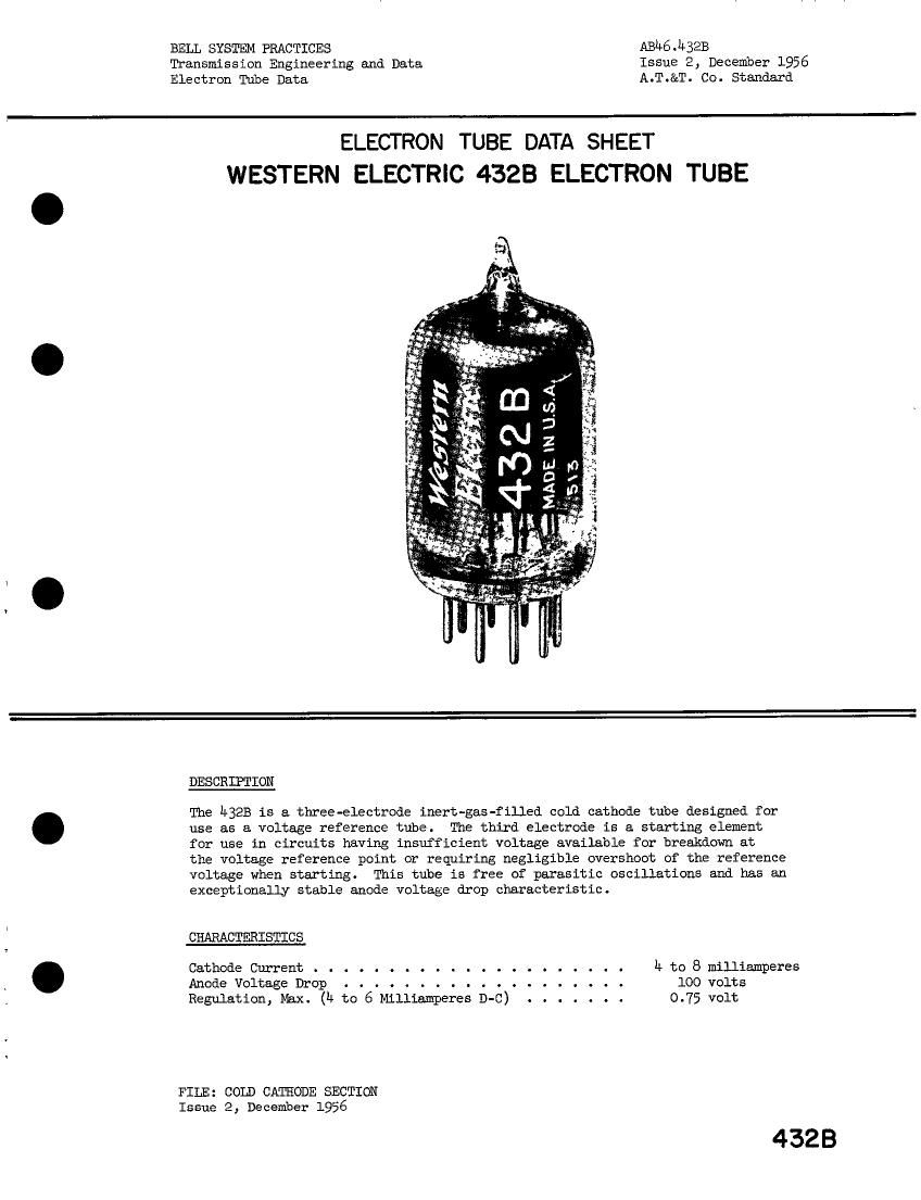
The h32B is a three-electrode inert-gas-filled cold cathode tube designed for
use as a voltage reference tube. The third electrode is a starting element
for use in circuits having insufficient voltage available for breakdown at

the voltage reference point or requiring negligible overshoot of the reference
voltage when starting. This tube is free of parasitic oscillations and has an
exceptionally stable anode voltage drop characteristic.

CHARACTERISTICS

Cathode Current . . . . . . . . . . . . . . . . . . . . . h to 8 milliamperes
Anode Voltage Drop . . . . . . . . . . . . . . . . . . . 100 volts
Regulation, Max. (h to 6 Milliamperes D-C) . . . . . . . 0.75 volt

FILE: COLD CATHODE SECTION
Issue 2, December 1956

4323

Page 2

h32B - Page 2
RATINGS, Absolute Values

Cathode Currentl
Maxizumn. . . . . . . . . . . . . . . . .
Minimun

Inverse Starter or Anoae Current, Maximum .

Starter Current, Minimum3

A:bient Temperature Limits

ELECiRICAL DATA, Throughout Life

Anode Breakdown Voltage .
Anode Voltage Drop at 6 Milliampe
Starter Breakdown Voltage .
Starter Voltage Drop at 0.2 ma
Transfer Current at 110 Anode Volts .
Regulation (L: to 6 Milliamperes, D-C) . . .

res (D-C)h

8 milliamperes
h milliamperes
0.0 milliampere
0.2 milliampere
-55 to + 60 centigrade

Temperature Sensitivity of Anode Voltage Drop

Anode Current, h Milliamperes ED-C; . . . .

Anode Current, 8 Milliamperes D-C . . . .
Fluctuationj . . . . . . . . . . . . . .
Stability................

MECHANICAL DATAz Throughout Life

Mounting Position .
Xet Weight, Approximate
Bulb
Base
Dinensions and Connections

Kate 1:

See outline dr wing

H1_n.Bogex Max.
. . --- 135 160 volts
. . 99 100 103 volts
. . --- 135 200 volts
. . --- 102 --- volts
. . --- 60 200 nicroamperes
. . -- 0.3 0.75 volt
. --- -o.01 --- volt/c
. -- -0.02 --- volt/c
. . -- 0.02 0.1 volt
. . --- 0.2 0.8 volt
. . . . . . . . . Any
. . . . . . . . . 0.3 ounce
T6-l/2
. . . . . . . . . Small Button 9-pin
Page 3

Sufficient resistance must be used in series with the tube to assure

that electrode currents do not exceed their maximum rated values.

Note 2: The tube is capable of operating

at current values below the ratEd

"Minimum" value of h milliamperes in regulator applications where
lower current is required, however, operation at values below b
milliamperes for extended periods of time (hundreds of hours) may
result in an increase in regulation.

Note

(a)

between starting operations

The minimum starter current requirement applies
when tube is operated for extended periods (hundreds of hours)

to assure maintaining starter break-

down and transfer characteristics.

('0)

These values are for new tubes.
within 3 minutes after starting.
be considered during tube life.

Note

Note The anode voltage drop variation

to assure oscillation-free operation.

Anode voltage drop will stabilize
The stability characteristic should

during a short period of tine (one

to ten minutes), with the tube operating at one value of current and
temperature within its ratings, will not exceed the above stated max-

imum value.

Note

The drift of anode voltage drop over a period of 1000 hours, with the

tube operating at one value of current and temperature within its

ratings, will not exceed the above stated maximum value.
After 1000-2000 hours operation the

improves with operating life.

Stability

drift of anode voltage drop per 1000 hours will not exceed 0.3 volt.