Western electric 432 a brochure
This is the 2 pages manual for western electric 432 a brochure.
Read or download the pdf for free. If you want to contribute, please upload pdfs to audioservicemanuals.wetransfer.com.
Extracted text from western electric 432 a brochure (Ocr-read)
Page 1
BELL SYSTEM PRACTICES SECTION ABL6.L32A
Transmission Engineering and Data Issue 1, October 1950
Electron Tube Data AT&T Co. Standard
. ADVANCE ELECTRON TUBE DATA SHEET
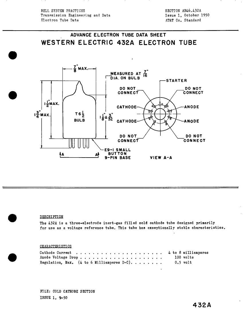
WESTERN ELECTRIC 432A ELECTRON TUBE
:gMAx. ..
r_MEASURED AT %
DIA.0N BULB -STARTER
no nor DO nor
CONNECT CONNECT
|é¥flAX.
CATHODE ANODE
I%MAX. '5 L" ;
'a*32
BULB CATHODE ANODE
L 4 no NOT no NOT
IU U U \\\- CONNECT connecr
as-IsMALL
{A M BUTTON
9-PIN BASE VIEW A-A
mmwmm
The L32A is a three-electrode inert-gas filled cold cathode tube designed primarily
for use as a voltage reference tube. This tube has exceptionally stable characteristics.
QHARAQIERISIIQS
Cathode Current ................ . . . . . b to 8 milliamperes
Anode Voltage Drop .................... 100 volts
Regulation, Max. (A to 6 Milliamperas D-C) ........ 0.5 volt
FILE: COLD CATHODE SECTION
ISSUE 1, 9-50
432A
Page 2
hBZA PAGE 2
A G b t V A
Cathode Current
Mexinun........................ 8milliamperes .
Minimum . . . . . . . . . . . . . . . . . . . . . . . . L nilliamperes
Maximum Inverse Starter or Anode Current . . . . . . . . . 0.0 milliampere
Starter Current (Minimum). . . . . . . . . . . . . . . . . . 0.2 nilliampere
Ambient Temperature Limits . . . . . . . . . . . . . . -55 to + 60 centigrede
ELZQIRIQAL_DAIA
Anode Breakdown Voltage . . . . . . . . . . . . --- --- 160 volts
Anode Voltage Drop at 6 Hillianperes (D-C)l. . . 99 100 103 volts
Starter Breakdown Voltage . . . . . . . . . --- --- 200 volts
Starter Voltage Drop . . . . . . . . . . . . . . -- 115 --~ volts
Required Transfer Current at 110 Anode Volts . . 200 --- --- microamperes
Regulation (L to 6 Hillianperes, D-C). . . . . . -- --- 0.5 volt
Temperature Sensitivity of Anode Voltage Drop
Anode Current, A Hillianperes (D-C) . . . . . --- -G.Ol -~ volt/e
Anode Current, 8 Hilliamperes (D-C) . . . . . -~- -0.02 --- volt/o
FluctuationZ.................. m 0.1 volt
Stability3................... --- 0.3m»;
HESHARIEAL_DAIA
Mounting Position . . . . . . . . . . . . . . . . . . . . . Any
Net Weight, Approximate . . . . . . . . . . . . . . . . . . 0.3 Ounce
Bulb . . . . . . . . . . . . . . . . . . . . . . T . . . . T 6-1/2
Base . . . . . . . . . . . . . . . . . . . . . . i . . . . Small Button 9-pin
Note 1: These values are for new tubes. The stability characteristic should he
considered during tube life.
Note 2: The anode voltage drop variation during a short period of time
(one to ten minutes), with the tube operating at one value of current and
tenperature within its ratings, will not exceed the above stated maximum value. .
Note 3: The drift of anode voltage drop over a period of 1000 hours, with the tube
operating at one value of current and temperature within its ratings, Will
not exceed the above stated maximum value.
A development of Bell Telephone Laboratories, the research laboratories of the . .
American Telephone and Telegraph Company and the Western Electric Company.
1-x-so~u PRINTED IN U.s.n. T-2687