Western electric 429 a brochure

This is the 4 pages manual for western electric 429 a brochure.
Read or download the pdf for free. If you want to contribute, please upload pdfs to audioservicemanuals.wetransfer.com.

Page: 1 / 4
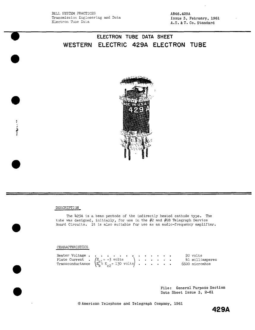
western electric 429 a brochure

Extracted text from western electric 429 a brochure (Ocr-read)


Page 1

BELL SYSTEM PRACTICES AB46.429A
Transmission Engineering and Data Issue 5, February, 1961

Electron Tube Data A.T. & T. Co. Standard

We

ELECTRON TUBE DATA SHEET
WESTERN ELECTRIC 429A ELECTRON TUBE

DESCRIPTION

The h29A is a beam pentode of the indirectly heated cathode type. The
tube was designed, initially, for use in the #2 and #9B Iblegraph Service
Board Circuits. It is also suitable for use as an audio-frequency amplifier.

CHARACTERISTICS

Heater Voltage . . . . . . . . . . . . . . 20 volts

Plate Current . Eel: -3 volts . . . . . . kl milliamperes
Transconductance Eb: E02: 130 volts . . . . . . 6600 micromhos

File: General Purpose Section
Data Sheet Issue 5, 2-61

CJAmerican Telephone and Telegraph Company, 1961

429A

Page 2

429A-PAGE2

GENERAL CHARACT ISTICS

ELECTRICAL DATA

Heater Voltage (Kate 1) . . . . . . . . . 20 volts
Heater Curr . . . . . . . . . . . . 1&0 gilliagpereg
Direct Intereiectr Capacitance: (« .31: external shield}
Grid t: Plate ( mum) . . . . . . . . 1.5 mi
Input . . . . . . . . . . . . . . 6.5 Pkg
Oqufit . . . . . . . . . . . . . . 5,0 hi

Cathode . . . . . . . . . . . . . Coazed unipotenLia;
Bulb . . . . . . . . . . . . . . 19

Base . . . . . . . . . . . . . . Button Ste: 9-Pin
Mounting Position . . . . . . . . . . gr ,

ivifiiiII-itflv13fiJIHGS, Absolute Syste.- (Kate 4)

Plat Vol:age . . . . . . . . . . . . . . 275 vglgg

Screen Gr
Plate SJ:
Plate Dis

Screen Grid Dissipation . . . . . . . . . . .

id Vclzage . . . . . . . . . . . . 159 Volts
ma

- watts
watts

rent a n n - . . a o u - - - v c

sipaticn . . . . . . . . . . . . .

Heater-Cathode Voltage . . . . . . . . . . . :5
Bulb IEmperature . . . . - . . . . . . . . _JV°CentiErade
MAXIMUM CIRCUIT VALUES
Grid Circuit Resistance:

For Fixed Bias . . . . . . . . . . . . 3,1 megohgs

or Cathode Bias. . . . . . . . . . . . o_3 megchgs

TY?:CAL OPERATING CONDITIONS AND CHARACTERISTZ 5
Plate Voltage . . . . . . . . . . . . . . I30 volts
Screen Grid . . . . . . . . . . . . 13C volts

Contra; Grid

Peak a-F


Zero Signal . . . . . . . . . _ ma
)raximum S'gnai P_a:e Current _ . . . _ , _ . . me.
Screen Grid Current . . . . . . . . 2.0 ms
al Screen Grid Current . . . . . . . 3.5 ma

Grid

(Hot/e 3, See Page 1L) . . . . . . 6600 umhos
. I . . . - . . . . . I . TCCO Ohms

Load Resistance. . . . . . . . . . . . . . 5000 ohms

Note 1:

Note 2:

o optimum life, the heater voltage should be regulated to within

% cf the rated value.

Fr
1 2

In the "Absolute System the maximur ratings specified are limiting
values above which the service -1t of the tube may be impaired
from the viewpoint of life and 55 factory performance. Maximum
ratings, as such, do not constitute a set of operating conditions
and all values may not, therefore, be attained simultaneously.