Western electric 425 a brochure
This is the 4 pages manual for western electric 425 a brochure.
Read or download the pdf for free. If you want to contribute, please upload pdfs to audioservicemanuals.wetransfer.com.
Extracted text from western electric 425 a brochure (Ocr-read)
Page 1
BELL SYSTEM PRACTICES SECTION AB46.425A
Transmission Engineering and Data Issue 4, June 1962
Electron Tube Data A.T.& T. Co. standard
6 ELECTRON TUBE DATA SHEET
WESTERN ELECTRIC 425A ELECTRON TUBE
DESCRIPTION 1
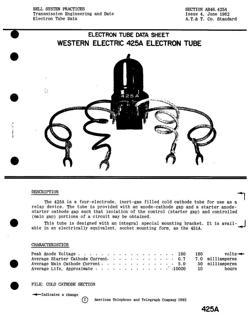
The 425A is a four»electrode, inert-gas filled cold cathode tube for use as a
relay device. The tube is provided with an anode-cathode gap and a starter anode-
starter cathode gap such that isolation of the control (starter gap) and controlled
(main gap) portions of a circuit may be obtained.
. This tube is designed with an integral special mounting bracket. It is avail-
able in an electrically equivalent, socket mounting form, as the 451A.
CHARACTERISTICS
Peak Anode Voltage. . . . . . . . . . . . . . . . 130 130 volts--
Average Starter Cathode Current- . - - - - . - - - - - 0.7 7.0 milliamperes
. Average Main Cathode Current- . - - . - - . - . - - - 5.0 50 milliamperes
Average Life, Approximate - . - . - - - - ~ - - . -' .10000 10 hours
. FILE: COLD CATHODE SECTION
-<-Indica.tes a change
American Telephone and Telegraph Company 1962
425A
Page 2
425A -PAGE 2
MAXIMUM RATINGS, Absolute System (Note 1)
Peak Voltage, Forward or Inverse
Anode to all other Electrodes . . . . . . . . . . . . . . . 130 volts
Cathode to all Other Electrodes - - - - - . - - - - - - - - 180 volts
->-Cathode Current (Note 2)
Peak . . . . . . . . . . . . . . . . . . . . . 50 milliamperes
Average . . . . . . . . . . . . . . . . . . . . . . . . 20 milliamperes
Averaging Time . - - - - - - . - ~ - - - - . - 2 seconds
Starter Cathode Current(Note2)
Peak . . . . . . . . . . . . . . . . . . . 7 milliamperes
Average . . . . . . . . . . . . . . . . . . . . . . . . 2_5 milliamperes
Averaging Time . - - - - - . . . - - - . 2 seconds
->-Peak Inverse Current (Note 2)
Anode. . . . . . . . . . . . . . . . . . . . . . . . 5 milliamperes
Starter Anode - '. - - - . - - - - . - - - - - - . . 1 milliamperes
Ambient Temperature Limits . . . . . . - . . . . . . -55° to +85° centigrade
ELECTRICAL DATA, Throughout Life
Min. Bogey Max.
Starter Breakdown voltage
Anode Voltage Drop at 10 Milliamperes . . . . . . 58 70 80 volts
sn~Tranafer Current (Note4). . . . . . . See Curve, Figure 3. Pagei
Negative Cathode Transfer Voltage (Note 5) . . . . - -25 -40 volts
Ionization Time, Starter Gap (Approx. )(Note 6% . . - 5 - milliseconds
Deionization Time, Main Gap (Approx.) . . . . . . - 1 - millisecond
MECHANICAL DATA
Mounting(Note7) . . . . . . . . . . . . . . . . . . . Any position
New Weight, Approximate . . . . . . . . . . . . . . 0.7 ounce
Dimensions and Connections . . . . . . . . . . . See outline drawing on page 4
HANDLING
This tube contains a small amount of krypton-85 gas which is a by-product
radioactive material. The amount of krypton-85 is less than five microcuries, which
is too small an amount to require any special care in use.
Atomic Energy Commission regulations require that the individual tube carton
for tubes containing by-product radioactive material be appropriately marked. The
marking includes the statement that tube disposal should be in approved manner.
Approved instructions for disposal of tubes containing krypton-85 are as
follows;
Tubes to be disposed of should be broken or crushed in a well
ventilated place releasing any resulting vapors to the outside
atmosphere. The residual broken or crushed tubes should be dis-
posed of in a normal public trash disposal system. Tubes should be
disposed of at a rate of not more than 100 each week from any one
location. Avoid breathing vapors from broken tubes.
-->-Indicates a change