Western electric 420 a brochure

This is the 4 pages manual for western electric 420 a brochure.
Read or download the pdf for free. If you want to contribute, please upload pdfs to audioservicemanuals.wetransfer.com.

Page: 1 / 4
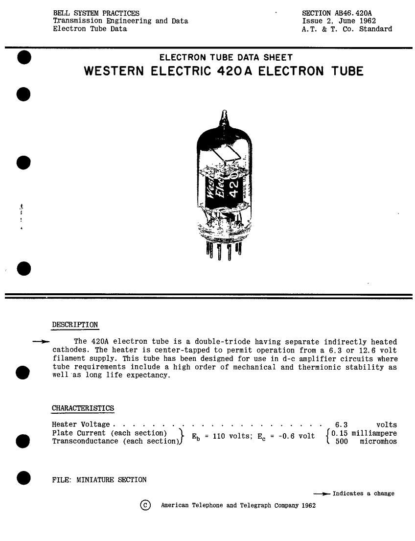
western electric 420 a brochure

Extracted text from western electric 420 a brochure (Ocr-read)


Page 1

BELL SYSTEM PRACTICES SECTION AB46.420A
Transmission Engineering and Data Issue 2, June 1962
Electron Tube Data A.T. & T. Co. Standard

, .- 7v.-

ELECTRON TUBE DATA SHEET
WESTERN ELECTRIC 420A ELECTRON TUBE

.._>.

DESCRIPTION

The 420A electron tube is a double-triode having separate indirectly heated
cathodes. The heater is center-tapped to permit operation from a 6.3 or 12.6 volt
filament supply. This tube has been designed for use in d-c amplifier circuits where
tube requirements include a high order of mechanical and thermionic stability as
well as long life expectancy.

CHARACTERISTICS

Heater Voltage - - - . - - - - . - 6.3 volts
Plate Current (each section) } _ 1t = _0 6 olt {0.15 milliampere
Transconductance (each section) Eb 110 vo S E ' V 500 micromhos

FILE: MINIATURE SECTION
->- Indicates a change

© American Telephone and Telegraph Company 1962

Page 2

420 A- PAGE 2

GENERAL CHARACTERISTICS . '
Electrical Data .
-- Parallel Ser1es
Heater Voltage . . . . . . . . . . . . . 6.3 12.6 volts
Heater Current . . . . . . . . 360 180 milliamperes
Direct Interelectrode Capacitances without with external
external shield shield (EIA #315)
Grid to plate (each section) . . . . . . . 1,4 (a) 1.4 uuf
Input (each section) . . . . . 1.5 (a) 1.7 uuf .
Output (Section #1). 0.8 (a) 1.5 uuf
Output (Section #2). 0.6 (a) 1.3 uuf
Plate 1 to Plate 2 . . . . . . . . . . . 0.9 (b) 0.8 upf
Grid 1 to Plate 2 . . . . . . . . . . . 0.01 (b) O 01 ugf
Grid 2 to Plate 1 . . . . . . . 0.01 (b) 0 01 uuf 1
Mechanical Data
Cathode . . . . . . . . . . . . . . . . . . . . . . . Coated Unipotential
Bulb . . . . . . . . . . . . . . . . . . . . . . . . . . . T 6%
Base . . . . . . . . . . . . . . . . . . . . . Small Button 9- pin
Mounting Position. . . . . . . . . Any
Dimensions and pin connections shown in outline drawing on Page 4 .
MAXIMUM RATINGS. Absolute System (Each Section) "
Plate voltage . . . . . . . . . . . . . . . . . . . . . . 225 volts
Plate Dissipation . . . . . . . . . . . . . . . . . . . . 1.0 watt-i-1
Plate Current . . . . . . . . . . . . . . . . . . . . 5 milliamperes
Heater- Cathode Voltage . . . . . . . . . . . . . . . . . . 75 volts
TYPICAL OPERATING CONDITIONS AND CHARACTERISTICS, D-C AMPLIFIER (See Fig. 1)
(Values are for each section unless otherwise specified)
Heater Supply Voltage - - . . - - - - - - . - - - - - - . 12.6 volts .
Heater Ballast Resistor . . . . . . . . . . . . . . . . . 35 ohms
Plate Supply Voltage . . . . . . . . . . 310 volts
Cathode Bias Resistor (Cathodes tied together) . . . . . . . 150,000 ohms
Plate Current. . . . . . . . . . . . . 0.15 milliampere
Grid Current (max.) . . . . . . . . . . . . . . . . . . . 10'9 ampere
Plate Resistance. . . . . . . . . . . . . . . . . . . . . 0.14 megohm
Load Resistance . . . . . . . . . . . . . . . . . . . . . 0.9 megohm
Transconductance . . . . . . . . . . . . . . . . . . . . 500 micromhos
Amplification Factor . . . . . . . . . . . . . . . . . . . 70 .
Balance1 . . . . . . . . . . . . . . . . . . . . . . . . 0.3 volt
Stability2 . . . . . . . . . . . . . . . . . . . . . . . 5 millivolts
(a) with external shield #315 connected to cathode pin of section under test. .

(b) With external shield #315 connected to ground with other elements.

-->-Indicates a change