Western electric 418 a brochure

This is the 4 pages manual for western electric 418 a brochure.
Read or download the pdf for free. If you want to contribute, please upload pdfs to audioservicemanuals.wetransfer.com.

Page: 1 / 4
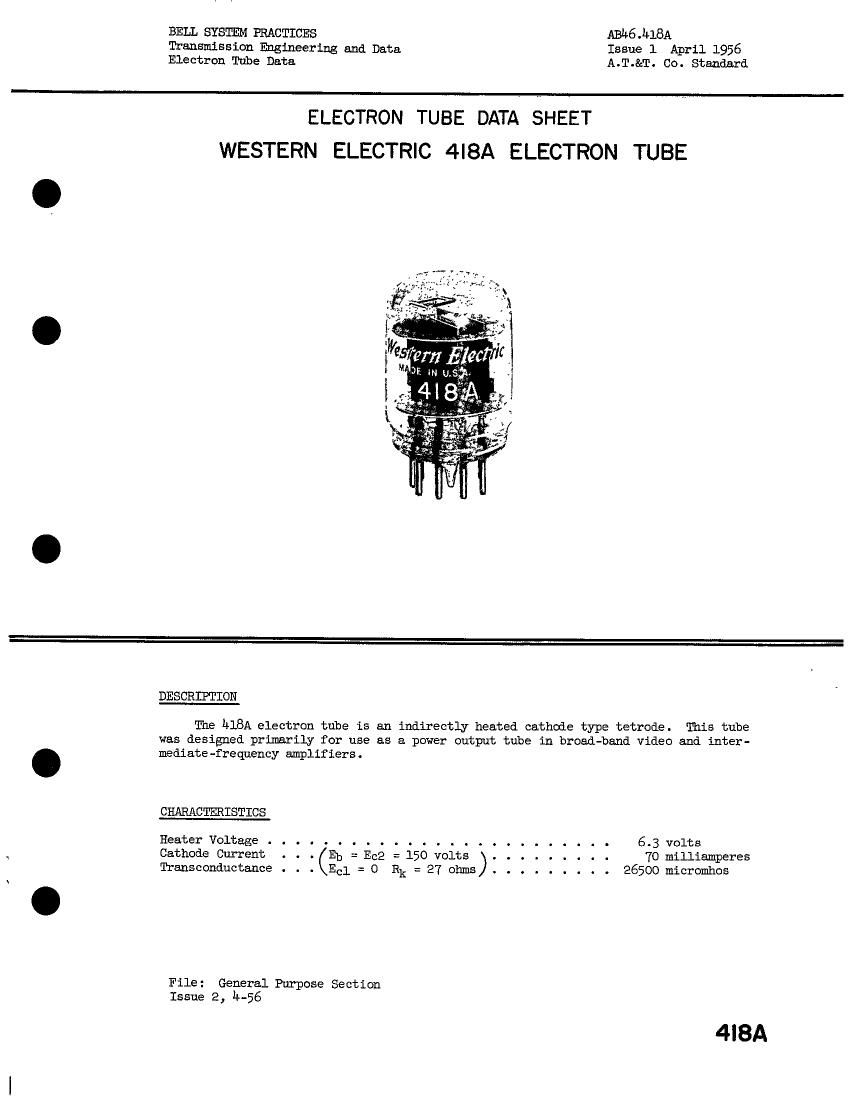
western electric 418 a brochure

Extracted text from western electric 418 a brochure (Ocr-read)


Page 1

BELL SYSTEM PRACTICES A1346Jl18A
Transmission Engineering and Data Issue 1 April 1956
Electron Tube Data A.T.&T. Co. Standard

ELECTRON TUBE DATA SHEET
WESTERN ELECTRIC 4|8A ELECTRON TUBE

II
II
II

._ .-

DESCRDTION

The hlBA electron tube is an indirectly heated cathode type tetrode. This tube
was designed primarily for use as a power output tube in broad-band video and inter-
mediate -frequeucy amplifiers .

CHARACTERISTICS

Heater Voltage ......................... 6.3 volts
Cathode Current . . . Eb = Ec2 = 150 volts ......... 7O miniamperes
Transconductance . . . Eel = 0 Rk = 27 ohms ......... 26500 micromhos

File: General Purpose Section
Issue 2, lT-56

4|8A

Page 2

hisA - Page 2

GENERAL CHARACTERISTICS
EIECTRICAL DATA
Heater Voltage . . . . . . . . .

Heater Current . . . . . . . . . . .
Direct Interelectrode Capacitances

GridtoPlate.... .. ..... ....
Input: $1 to (h+k+g2+i s) . . . . . . . . . . . .

Output: 9 to (h+k+g2+i. s) . . . . . . . .
MECHANICAL DATA

Cathode . . . . . . . . . . . . . . . . . . . .

Bulb . . . . . . . . . . . . . . . . . . . . . .

Base . . . . . . . . . . . . . . . . . . .
Mounting Position . . . . . . . . .

Dimensions and pin connections shown in outline drawing

MAXIMUM RATIEGS, Design Center Values

Plate Voltage . . . . . .
Screen Grid Voltage . . .
Plate Dissipation . . . .
Screen Grid Dissipation .
Control Grid Dissipation
Cathode Current . . . . .
Heater-Cathode Voltage .
Bulb Eenperature . . . . . .

MAXIMUM CIRCUIT VAIUES

Grid Circuit Resistance:
For Fixed Bias . . . . . . . . . . . . . . . .
For Cathode Bias . . . . . . . . . . . . . . .

TYPICAL OPERATING CONDITIONS AND CHARACTERISTICS

Plate Voltage . . . . . . . . . . . . . . . . . .
Screen Grid Voltage . . . . . . . . . . . . . . .
Control Grid Voltage . . . . . . . . . . . . . .
Cathode Bias Resistor . . . . . . . . . .....
Plate Current . . . . . . . . . . . . . . . . . .
Screen Grid Current ...... . . . . . . . . .
Plate Resistance . . . . . . . . . .......
Transconductance . . . . . . . .
Control Grid Voltage (approximate) for

Plate Current of 10 microanperes . . . . . . . .

6.3 volts
0.6 ampere

Without

External

Shield

120
120
-1.0
#7
20
18000
26500

-9-5

Coated

19

See outline drawing page 4

Am;
Page 4

. . O
. . O

150
150
27

50

20
18000
26500

0-055 Huf
15-0 uuf
2.8 puf

Unipotential

250 volts

150 volts

8.5 watts

3.0 watts

see footnote *
90 milliamperes
90 volts
130 centigrade

.05 megohm
.10 megohm

volts

volts

volts

ohms
milliamperes
milliamperes

micromhos

volts

* Operation with the control grid positive with respect to the cathode is not

reconmended.