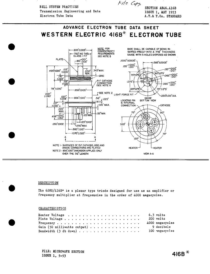
Western electric 416 b brochure
This is the 2 pages manual for western electric 416 b brochure.
Read or download the pdf for free. If you want to contribute, please upload pdfs to audioservicemanuals.wetransfer.com.
Extracted text from western electric 416 b brochure (Ocr-read)
Page 1
BELL SYSTEM PRACTICES
Transmission Engineering and Data
Electron Tube Data
Ff/C 6/7,
SECTION ABL6.L16B
ISSUE 1, MAY 1953
A.T.& T.CO., STANDARD
ADVANCE ELECTRON TUBE DATA SHEET
WESTERN ELECTRIC 4IGB* ELECTRON TUBE
.. .. N915 FOR
--335 3.005 CONCENTRICITY
#750140 mo, REQUIREMENTS
CLASS I FIT SEE NOTE 5
PLATE\ .mOOI"
Iao "
I: -.003
I .. \-r
4991030"II'£,2055" IIZACIJIIH _343"MA><.
I - '
.I70 __ GRID
1.020 /
7sI 1030"
I437:
1.090 .0377,
1006
~-.ass":,oos"-
~-856"i0|0"~-~
[s-Ir-L7 Tfi"
$030" I FONS MAX.
I .33 R-F CATHODE
+020" I CONNECTION
1- (SEE NOTE I)
.3I2"
.02 5
l
220"
MAX
I ..
wooo
I8 06:.
I
.. TI_-- .. |
J Tfi'fi MIN J35 MN
.050'3002
gV»----I25toos"
1250"MAX
--.eso":ol5"--I
I 0761020"
I_-..____I
NOTE |- SURFACES OF R-F CATHDDE.GRID AND
ANOOE CONNECTIONS ARE PLATED
NOTE 2 - 856'3.0I0"DIMENSION APPLIES ONLY
OVER THE 3I2" LENGTH
.Iooo":ooos
BASE SHAL
L BE CAPABLE OF BEING IN-
SERTED FREELY INTO A 7/IG" THICKNESS
GAUGE WITH 5 HOLES DISPOSED AS SHOWN
58520005"
..+00 1'
I35 mo? X/WV'KHOOO"
. ' -ZOOI'
_[5EE NOTE 2 LIGHT FORCE FIT
90°:o5' ..
w, TIA: "+900"
75 - / .065 -.oOI
L375" 11 i .. ..
wage--
|20'iO°5 \ 75°:O°5'
.250":OOI"DIA,
GAUGE
LOCATING PIN BOTTOM VIEW
a INTERNAL
CONNECTION CATHODE
75° 90°
4
520" 4*
I
T
.
\E vs
120'
\
HEATER J - HEATER
VIEW A-A
DESCRIPTION
The 6280/A16B' is a planar type triode designed for use as an amplifier or
frequency multiplier at frequencies in the order Of 1.000 megacycles.
CHARACTERI STI CS
Heater Voltage . . . .
Plate Voltage . . . . .
Frequency . .
Gain (50 millfwatts output) . . . .
Bandwidth (3 db down) .
FILE: MICROWAVE SECTION
ISSUE 1, 5-53
6.3 volts
20 volts
#000 megacycles
9 decibels
100 negacycles
4I63*
Page 2
6280/4165
GENERAL CHARACTERISTICS
ELECTRICAL DATA
Heater Voltage(3) . . . . . . . . . . . . ~-- 6.3 :::_ volts
Heater Current ..... . . . . . . . . --- 1.18 --- amperes
Amplification Factor . ...... . . . --- 200 ---
Transconductance (Ib - 30 ma) . . . . . . --- 50000 --- nicromhos
Direct Interelectrode Capacitances
Grid to Plate . . . . . . . . . . . . . 1.25 1.L5 1.60 uuf
Grid to sne11(h). . ....... . . . 8.5 11.2 17.0 uuf
Grid to Sheiijh) Hot (Ef;6.l v; Eb-O v) 7.6 3.7 10.3 uuf
Plate to sne11(b) . . . . . . . . . . . --- .019 .050 uuf
Cathode to Shell 30 A2.5 57 uuf
MECHANICAL DATA
Cathode . . . . . . . . . . ....... . . . . . . . . . . Unipotential
Mounting Position . . . . . . . . . ....... . . . . . . Any
Height, Approximate . . . . . . . . . . . . . . . . . . . . . 1 ounce
Socket . . . . . . . . . . . . . . . . . (Equivalent to or). KSlhlSL
MAXIMUM RATINGS! ABSOLUTE VALUES
Plate Voltage . . . . . . . . . . . . . . . . . . . . . 270 volts
Grid Voltage . . . . . . . . . . . . . . . . . . . . . { +1.5 volts
-15.0 volts
Plate Current . . . . . . . . . . . . . . . . . . . . . 33 nilliamperes
Grid Current . . . . . . . . . . . . . . . . . . . . . 15 nilliamperes
Plate Dissipation . . . . . . . . . . . . . . . . . . . 7.5 watts
Plate Seal Temperature . . . . . . . . . . . . . . . . 150' Centigrade
Grid Seal Temperature . . . . . . . . . . . . . . . . . 100 Centigrade
Heater-Cathode Voltage . . . . . . . . ..... . . . A5 volts
TYPICAL OPERATING CONDITIONS AND CHARACTERISTICS
Plate Voltage . . . . . . . . . . . . . . . . . . . . . 200 volts
Plate Current . . . . . . . . . . . . . . . . . . . . . 30 nilliamperes
Bias Circuit
Cathode Bias Resistor . . . . . . . . . . . . . . . . 260 ohms
Grid Supply Voltage . . . . ..... . . . . . . . . 8 volts
Frequency . . . . . . . . . . . . . . . . . . . . . . . 4000 megacycles
Gain (50 Hilliwatts Output) . . . . . . . . . . . . . . 9 decibels
Gain (500 Hilliwatts Output) . . . . . . . . . . . . . 5 decibels
Band Width (3 db Down) . ..... . . . . . . . . ._. 100 megacycles
Note (3): For optimum life, heater may be supplied from a source of 10.8 i 0.2
volts through a circuit resistance of L.16 ohms.
Note (A): Cathode connected to shell through cathode to shell capacitance.
Note (5): With the .750"-L0 thread acrewed into a guage having a thread with
a .750"-A0 class 1 fit,the .856", 1.070" and .180" diameters must
fit in cylinders concentric with the .750"-L0 thread and having
diameters of .895" x .720 long; 1.135" x .157" long; and .210" x
.375" long. Allowances for these tolerances must be made in any
circuit design.
1-9-53-1 PRINTED IN U.S.A. r2726