Western electric 408 a brochure

This is the 5 pages manual for western electric 408 a brochure.
Read or download the pdf for free. If you want to contribute, please upload pdfs to audioservicemanuals.wetransfer.com.

Page: 1 / 5
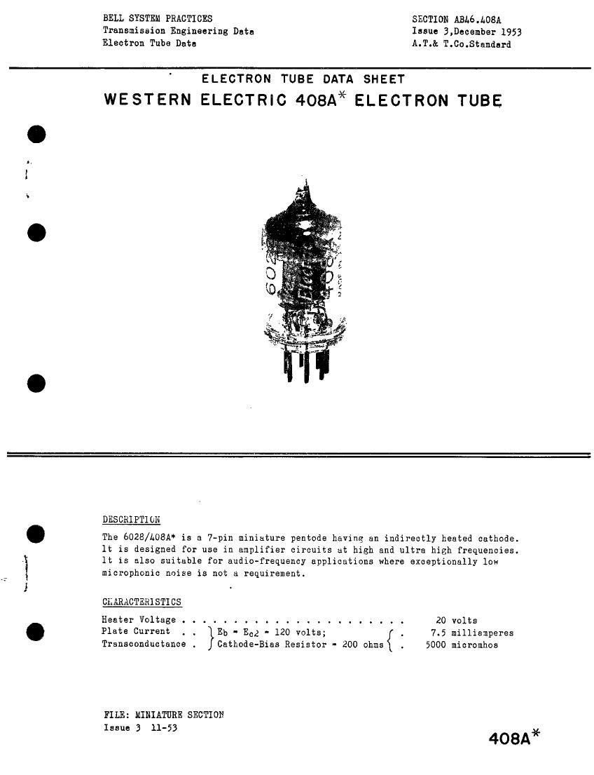
western electric 408 a brochure

Extracted text from western electric 408 a brochure (Ocr-read)


Page 1

BELL SYSTEM PRACTICES SECTION ABL6.L08A
Transmission Engineering Data Issue 3.December 1953
Electron Tube Data A.T.& T.Co.Standard

ELECTRON TUBE DATA SHEET
WESTERN ELECTRH3408A*ELECTRON TUBE

i

Z
V:
5;
2

Mag-.-

DESCRIPTION

The 6028/A08A* is a 7-pin miniature pentode having an indirectly heated cathode.
1t is designed for use in amplifier circuits at high and ultra high frequencies.
It is also suitable for audio-frequency applications where exceptionally low
microphonic noise is not a requirement.

CKARACTERISTICS

Heater Voltage . . . . . . . . . . . . . . . . . . . . . . 20 volts
Plate Current . . Eb . Ecg - 120 volts; . 7.5 milliemperes
Transconductance . Cathode-Bias Resistor - 200 ohms { 5000 micromhos

FILE: MINIATURE SECTIOH
Issue 3 11-53

408A*

Page 2

6028/L08A-Page 2

GENERAL CHARACTERISTICS
ELECTRICAL DATA

Heater Voltage, A-C or D-C ..... . . . . . . . . . . 20 volts
Heater Current . . . . . . . . . . . . . . . . . . . . . 50 nilliamperes
Direct Interelectrode Capacitances . . . without with
external shield externa# shield
(an; 316)

Grid to Plate (maximum) . . . . . . . .019 *.010 uuf
Input . . . . . . . . . . . . . . . . 3.9 *L.0 uuf
Output . . . . ........ . . . . 2.0 *2.9 uuf

HECHANICAL DATA
Cathode . . . . . . . . . . . . . . . . . . . . Coated Uninotentisl

Bulb . . . . . . . . . . . . . . . . . . . . . . T5 1/2

Base . . . . . . . . . . . . . . . . . . . . . . Hiniature Button 7-pin

Mounting Position . . . . . . . . . . . . . . . Any
Dimensions and pin connections shown in outline drawing on Page 5
JAIIEUH RATINGS, Design-Center Values
Plate Voltage . . . . . . . . . . . . . . . . . . . . . 180 volts

Screen Grid Voltage . . . . . . . . . . . . . . . . . . 1A0 volts
Plate Dissipation . . . . . . . . . . . . . . . . . . . 1.7 watts
Screen Grid Dissipation . . . . . . . . . . . . . . . . 0.5 wutt
Cathode Current . . . . . . . . . . . . . . . . . . . . 18 nillianperea
Heater-Cathode Voltagel . . . . . . . . . . . . . . . . 120 volts
Bulb Temperature . . . . . . . . . . . . . . . . . . . . 120°oentigrade
Haximum Grid Current Resistance for
Fixed Bias . . . . . . . . . . . . . . . . . . . . . . l.0 megohm
Cathode Bias . . . . . . . . . . . . . . . . . . . . . 2.0 megohms

TYPICAL CPERATIKG CCNDITIONS AND CHARACTERISTICS - CLASS Al AMPLIFIER

Plate Voltage . . . . . . . . . . . . . . , . 120 120 volts

Screen Grid Voltage . . . . . . . . . . . . . lZO 120 volts
Cathode-Bias Resistor . . . . . . . . . . . . 200 130 ohms
Peak A-F Grid Voltage . . . . . . g . . . . . 2.0 1.5 volts
Zero Signal Plate Current . . . . . . . . . . 7.5 9.4 nilliamperes
Maximum Signal Plate Current . . . . . . . a . 7.7 9.2 milliamperes
Zero Signal Screen Grid Current e . . . . . . 2.5 3.2 millipmperes
Maximum Signal Screen Grid Current , . . . . s 3a3 3.9 millianperes

Plate Resistance . . . . a . . . . . . . . . . 0.30 0,25 megohm

Transconductance . . . . . . . . . . . . . . e 5000 5600 micromhos
Load Resistance . . . . . . . . . . . . . . . 15000 15000 ohms

Power Output . . . . . . . . . . . . . . . . 325 265 milliwatts
Total Harmonic Distortion . . . . . . . . . e 12 5.5 per cent
Grid Voltage, Approximate, for

Plate Current of 10 Microamperes . . . . . . -6.8 -6.8 volts

* External shield connected to cathode pins 2 and 7:

Note 1. For optimum tube life it is recommended that heater-cathode
voltage should not exceed 90 volts: