Western electric 405 a brochure
This is the 4 pages manual for western electric 405 a brochure.
Read or download the pdf for free. If you want to contribute, please upload pdfs to audioservicemanuals.wetransfer.com.
Extracted text from western electric 405 a brochure (Ocr-read)
Page 1
BELL SYSTEM PRACTICES fl
Transmission Engineering Data
Vacuum Tube Data
SECTION AB 46.405A
Issue 2, January 1950
A.T.&T. Co. Standard
COLD CATHODE Western Electric
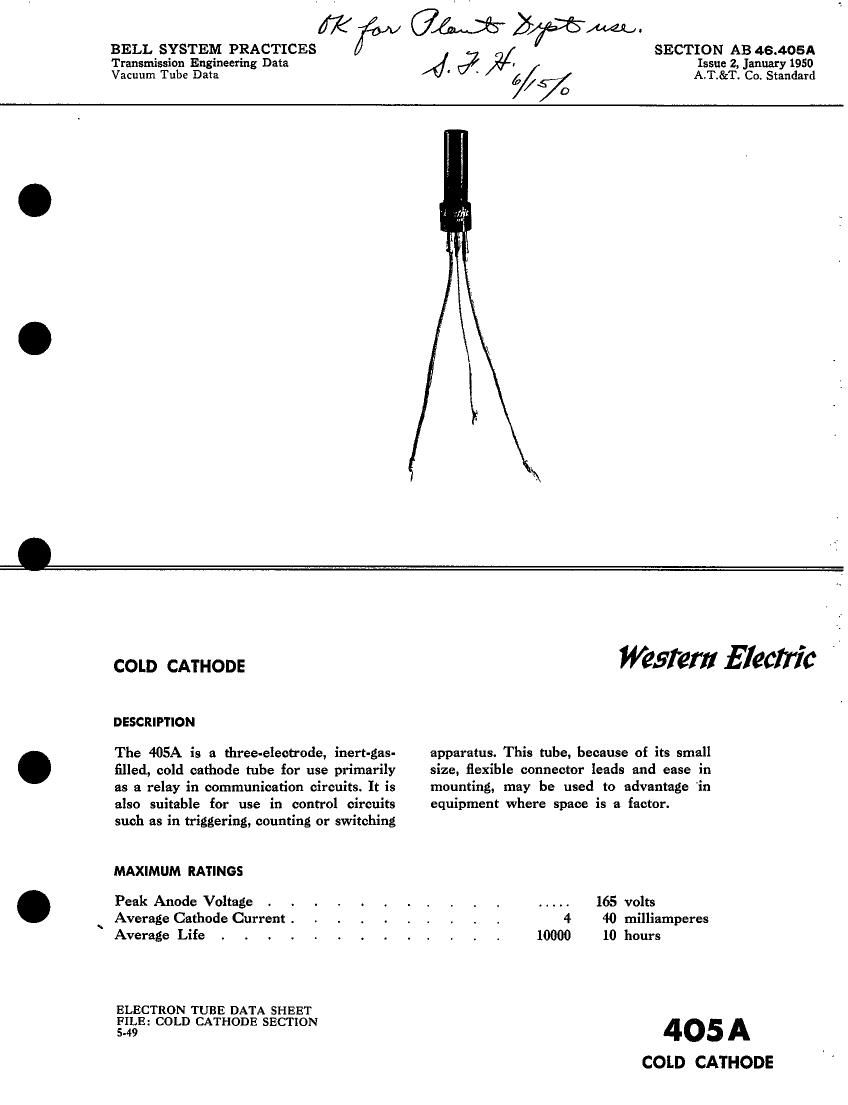
DESCRIPTION
The 405A is a three-electrode, inert-gas- apparatus. This tube, because of its small
filled, cold cathode tube for use primarily size, flexible connector leads and ease in
as a relay in communication circuits. It is mounting, may be used to advantage 'in
also suitable for use in control circuits equipment where space is a factor.
such as in triggering, counting or switching
MAXIMUM RATINGS
Peak Anode Voltage . . . . . . . t . ..... 165 volts
Average Cathode Current . . . . . . . . . . 4 40 milliamperes
Average Life . . . . . . . . . . . . . 10000 10 hours
ELECTRON TUBE DATA SHEET
FILE: COLD CATHODE SECTION
5.49 405A
COLD CATHODE
Page 2
405A-PAGE 2
MAXIMUM RATINGS, Absolute Values
Peak Anode Voltage
Forward . . . . . . . . . . . . . . 1$ volts
Inverse . . . . . . . . . . . 165 volts
Forward Cathode Current
Peak . . . . . . . . . . . . . . . 40 milliamperes
Average . . . . . . . . . . . . . . 15 milliamperes
Averaging Time . . . . . . . . . . . 1 second
Peak Inverse Anode Current . . . . . . . . . 1 milliampere
Ambient Temperature Limits . . -. . . . . . . -55 to +85 centigrade
ELECTRICAL DATA
Min. Bogey Max.
Starter Breakdown Voltage' . . . . . . . 67 75 89 volts
Starter Voltage Drop at 10 milliamperes . . . . . 52 60 74 volts
Anode Voltage Drop at 10 milliamperes. . . 66 75 90 volts
Required Transfer Current at 130 Anode Volts (D. C. ) . 50 . . . . . . microamperes
Deionization Time, Approximate
Starter Gap 2 milliseconds
Main Gap . 8 . milliseconds
MECHANICAL DATA
MountingPosition.........,.,.....Any
Net Weight, Approximate . . . . . .. . . . . . . . . 0.4 ounce
Limits apply immediately after tube has conducted current. It tube
has been idle, these values may be as much u 3 volt! higher or lower.
:60 TRANSFER CURRENT CHARACTERlSTlC
. ; (TYPICAL)
150
140
130
120
ANODE VOLTAGE IN VOLTS
IlO
9O
0 IO 20 30 40 50 60
TRANSFER CURRENT IN MICROAMPERES