Western electric 403 b brochure

This is the 4 pages manual for western electric 403 b brochure.
Read or download the pdf for free. If you want to contribute, please upload pdfs to audioservicemanuals.wetransfer.com.

Page: 1 / 4
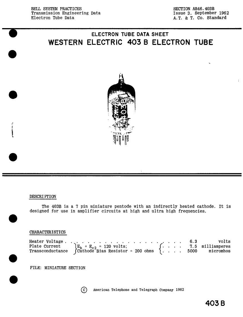
western electric 403 b brochure

Extracted text from western electric 403 b brochure (Ocr-read)


Page 1

BELL SYSTEM PRACTICES SECTION AB46.4OBB
Transmission Engineering Data Issue 3, September 1962

Electron Tube Data A.T. & T. Co. standard

ran- «a a.

ELECTRON TUBE DATA SHEET
WESTERN ELECTRIC 403 B ELECTRON TUBE

DESCRIPTION

The 4033 is a 7 pin miniature pentode with an indirectly heated cathode. It is
designed for use in amplifier circuits at high and ultra high frequencies.

CHARACTERISTICS

Heater Voltage . . . . . . . . . . . . . . . . . . . . . 6.3 volts
Plate Current Eb = E62 = 120 volts; . . . . 7.5 milliamperes
Transconductance Cathode Bias Resistor = 200 ohms 5000 micromhos

FILE: MINIATURE SECTION

(Z) American Telephone and Telegraph Company 1962

403 B

Page 2

403 B - PAGE 2

GENERAL CHARACTERISTICS

Electrical Data

Heater Voltage, A-C or D-C (Note 1).. . . . . . . . . . . 6.3 volts
Heater Current. . . . . . . . . . . . . . . 150 milliamperes
Direct Interelectrode Capacitances . . . . . ,without with

external shield external shield
(JEDEC #316)

Grid to Plate (maximum) . . . . . . . . . .019 .010 uuf

Input: g1 to (h+k+g2+g3+i.s.). . . . . . . 3.9 * 4.0 unf

Output: p to (h+k+g2+g3+i.s.) . . . . . . . 2.0 * 2.9 nuf
Mechanical Data

Cathode . . . . . . . . . . . . . . . . . . . . . . Coated Unipotential
Bulb T 5);.
Base .'."..'IIIIIIIIfII.'.'IIIIfMiniatureButtoMpin
Mounting Position _ Any
Dimensions and pin connections shown in outline drawing on Page 4.
MAXIMUM RATINGS, Absolute System (Note 2) i I
Plate Voltage . . . . . . . . . . . . . . . . . . . . 200 volts
Screen Grid Voltage . . . . . . . . . . . . . . . . . 155 volts
Plate Dissipation . . . . . . . . . . . . . . . . . . 1,35 watts
Screen Grid Dissipation. . . . . . . . . . . . . . . . 0.55 watt
Cathode Current . . . . . . . . . . . . . . . . . . . 20 milliamperes
Heater Cathode Voltage . . . . . . . . . . . . . . . . 130 volts
Bulb Temperature. . . . . . . . . . . . . . . . . . . 130 centigrade

Maximum Grid Circuit Resistance
For Fixed Bias . . . . . . . . . . . . . . . . . . . 1,0 megohm
For Cathode Bias . . . . . . . . . . . . . . . . . . 2_o megohmsl

TYPICAL OPERATING CONDITIONS AND CHARACTERISTICS ~ Class A1 Amplifier

Plate Voltage. . . . . . . . . . . . . . . 120 150 180 volts
Screen Grid Voltage . - - - - - - - - 120 140 120 volts
Cathode Bias Resistor (Note 3) - - - - - - - 200 330 200 ohms
Plate Current . . . . - . - - - - - - 7.0 6.6 7.4 milliamperes Screen Gird Current- - - . . - ~ - - - . - - 2,2 2.1 2.1 milliamperes<-
Plate Resistance . . . - - . - - - - - - - 0.30 0.40 0.45 megohm
Transconductance . - - - - - - - - - - 5000 4500 5100 micromhos
Grid Voltage, Approximate, for

Plate Current of 10 Microamperes- -6.8 -7.8 -6.9 volts
External shield connected to cathode pins 2 and 7. 4-

Note 1: For optimum tube life the heater voltage specified (6.3 volts) should be regulated to i515.

Note 2: In the Absolute System" the maximum ratings specified are limiting values above which the
serviceability of the device may be impaired from the viewpoint of life and satisfactory
performance. Maximum ratings, as such, do not constitute a set of operating conditions and
all values may not, therefore, be attained simultaneously.

Note 3: Operation with the control grid positive with respect to the cathode is not recommended.

«Indicates a change