Western electric 396 a brochure

This is the 4 pages manual for western electric 396 a brochure.
Read or download the pdf for free. If you want to contribute, please upload pdfs to audioservicemanuals.wetransfer.com.

Page: 1 / 4
western electric 396 a brochure

Extracted text from western electric 396 a brochure (Ocr-read)


Page 1

BELL SYSTEM PRACTICES SECTION ABIL6.396A
Transmission Engineering and Data Issue 2, November 1951!-
Electron Tube Data A.T.&T. Co. Standard.

ELECTRON TUBE DATA SHEET
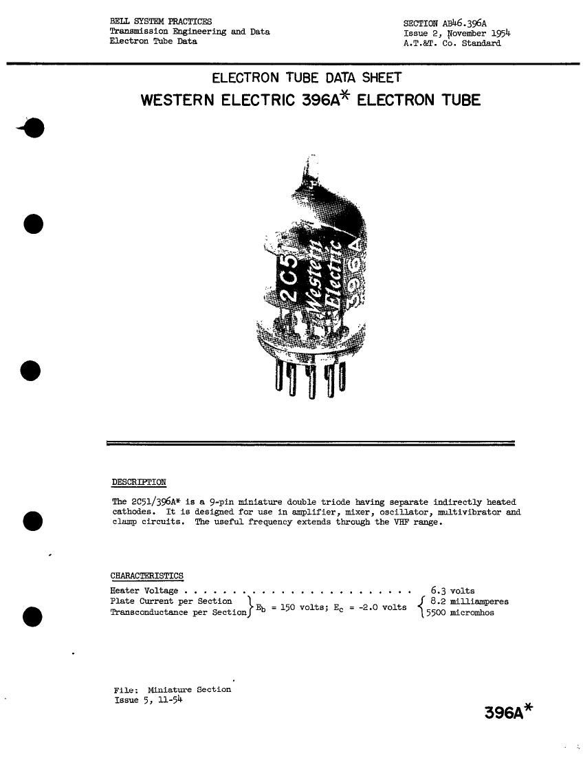
WESTERN ELECTRIC 396A* ELECTRON TUBE

izfc'

{$3
.N.
34

«a.

DESCRIPTION

The 2051/396A* is a 9-pin miniature double triode having separate indirectly heated
cathodes. It is designed for use in amplifier, mixer, oscillator, multivibrator and
clamp circuits. The useful frequency extends through the VHF range.

CHARACTERISTICS

Heater Voltage . . . . . . . . . . . . . . . . . . . . . . . . 6.3 volts
Plate Current per Section 8.2 milliamperes
Transconductance per Section}% _ 150 volts, EC - 4'0 volts 5500 micromhos

File: Miniature Section
Issue 5, 11-514.

396A*

Page 2

zeal/396A - Page 2

GENERAL CHARACTERISTICS
ELECTRICAL DATA

HeaterVoltage.......................
HeaterCurrent.......................

Direct Interelectrode Capacitances . . . . without

external shield.

with
external
EMMA

Grid to Plate per Section . . . . . . 1.3
Input per Section: 3 to (h+k+i.s.) . . 2.2
Output per Section: p to (h+k+i.a.) . 1.0
Plate-to-Plate............ 0.0!;
Plate-to-Plate, hhximum . . . . . . . 0.];

MECHANICAL DATA

Cathode......
Base........
MountingPosition.

.-..
u...

*l.3
*2.3
*l.3

6 . 3 volts
300 miniamperes

shield
1
uuf
uuf
uuf

0.03 uuf
0.10 uuf

Coated Unipotential

ESL/2

Small Button, 9-pin

ARV
Dimensions and pin connections shown in outline drawing on Page 1+

MAXIMUM RATINGS, DeHigu-Center Values (Each Section)

Plate Voltage . . . . .
Plate Dissipation . . .
PlateCun-ent . . . . .
Grid. Dissipation . . . .
Heater-Cathode Voltage .

Bulb Temperature . . .

. . . . , .
. . . . . -
. . o - . .
. . . . . .
. . . . . .
. . o . . .
. . . . c o
. o . . . .
o . . o . .
. . . . . .
. o . . . .

mimum Grid. Circuit Resistance for
FixedBias......................
CathodeBias.....................

TYPICAL OPERATING CONDITIONS AND CHARACTERISTICS - CLASS

.u.-.~

.-o.t.

(Each Section)

Plate Voltage . . .
GridVoltage . . . . . . .
Cathode Resistor . .
PlateCurrent
'lransconductance . . . . . .
Annihfication Factor
Grid Voltage (approximte) for

Plate Current of 10 microamperes . . . . . . . . .

. . . .
o . . .
. . . ~ . a
. . - . . .
. . . o . .
. . . .
. o o . . o
. . . .
. . . . . a

300 volts
1.5 Watts
18 milJJamperes
0.1 watt
90 volts
120° centigrade

. . l megohm
. . 2 megohms
A1 AMPLIFIER
150 150 volts
-2.0 --- volts
--- 2140 ohms
8.2 5.2 milliamperee
5500 5500 miCrcunhos
35 35
-8 --- volts

* Pin 5 and external shield (REIMA #315) connected to cathode pin of section

under test. Elements of other section grounded.

H Pin 5 and external shield (Rm #315) connected to ground. with other

elements .