Western electric 357 b brochure

This is the 6 pages manual for western electric 357 b brochure.
Read or download the pdf for free. If you want to contribute, please upload pdfs to audioservicemanuals.wetransfer.com.

Page: 1 / 6
western electric 357 b brochure

Extracted text from western electric 357 b brochure (Ocr-read)


Page 1

§;'§.w

it}

3s

BELL SYSTEM PRACTICES
Transmission Engineering Data
Vacuum Tube Data

TRIODE

AMPLIFIER, OSCILLATOR OR MODULATOR

DESCRIPTION

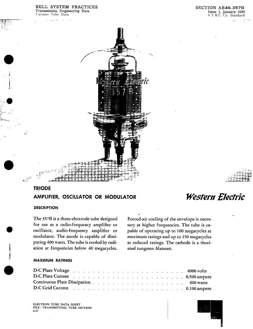
The 357B is a three-electrode tube designed
for use as a radio-frequency amplifier or
oscillator, audio-frequency amplifier or
modulator. The anode is capable of dissi-
pating 400 watts. The tube is cooled by radi-
ation at frequencies below 40 megacycles.

MAXIMUM RATINGS

D-C Plate Voltage
D-C Plate Current
Continuous Plate Dissipation ,
D-C Grid Current

ELECTRON TUBE DATA SHEET
FILE: TRANSMITTING TUBE SECTION
647

SECTION AB46.357B
Issue 1, January 1950
A T &T. Co Standard

0

Forced-air cooling of the envelope is neces-
sary at higher frequencies. The tube is ca-
pable of operating up to 100 megacycles at
maximum ratings and up to 150 megacycles
at reduced ratings. The cathode is a thori-
ated tungsten filament.

4000 volts
0.500 ampere
400 watts
0.100 ampere

Western Electric

Page 2

357B - PAGE 2

GENERAL CHARACTERISTICS

ELECTRICAL DATA

Filament Voltage _ . . . .
Filament Current at Bogey Voltage
Filament Starting Current
Filament Resistance, Cold
Amplification Factor
Conditions: Ir. : 200 ma, E]: = 2 kv .
Interelectrode Capacitances
Grid-Plate
Grid-Filament .
Plate-Filament _ . . . .
Maximum Usable Cathode Currentl

MECHANICAL DATA

MountingPosition . . . . . . . . . . . .
TypeofCoolingz. , _ . , . . . . . . ..
Required Air F low on Envelope
When Operated Above 40 Megacycles , .
Maximum Incoming Air Temperature . .
Maximum Glass Temperature. . . . . .
Shock and Vibration
Ruggedness (duration of 5 milliseconds) .
Natural Frequency of Elements
Plate..............
Filament-Grid Structure
Net Weight, approximate

Min. Bogey Max.
9.5 10.0 10.5 volts
9.7 10.0 10.5 amperes
50 amperes
0.12 ohm

27 30 34

3.5 4.25 5.0 uuf
10.0 11.5 13.0 uuf
2.0 2.5 4.0 uuf

2.5 amperes

, Vertical, plate terminal up
. . . . Radiation or forced-air

40 cfm
. . , . . . , 45 centigrade
. . . . . . , . . . 200 centigrade
. . . . . . . _ 50 G
100 cycles

75 cycles

13 ounces

l. Represents maximum usable cathode current for tube
as plate current plus grid current for any condition of
operation.

2. Radiation cooling is adequate hen the tube is operated
below 40 megaqcles and with a free circulation of air
around the tube. It operated in a confined space or at a
frequency abuse 40 megacycles. forced-air cooling is
necessary. Satisfactory air cooling will he obtained from
a blower delivering approximately 40 cubic leer of air
per minute from a l-inch diameter nozzle. The nozzle
outlet should be placed approximately 3 inches from the

tube and directed toward the central point of the enve-
lope. midway between the plate and grid terminals.

The plate terminal connector shall be of a design that
will readily conduct but from the plate terminal.

. This test is equiValeut to a JAN-1A Pendulum Bump

Tester l5: test. The data given represent the maximum
capabilities of the tube without electriml potentials ap«
plied and should not be construed to mean that the tube
is capable of withstanding an infinite number of shocks
of this magnitude.