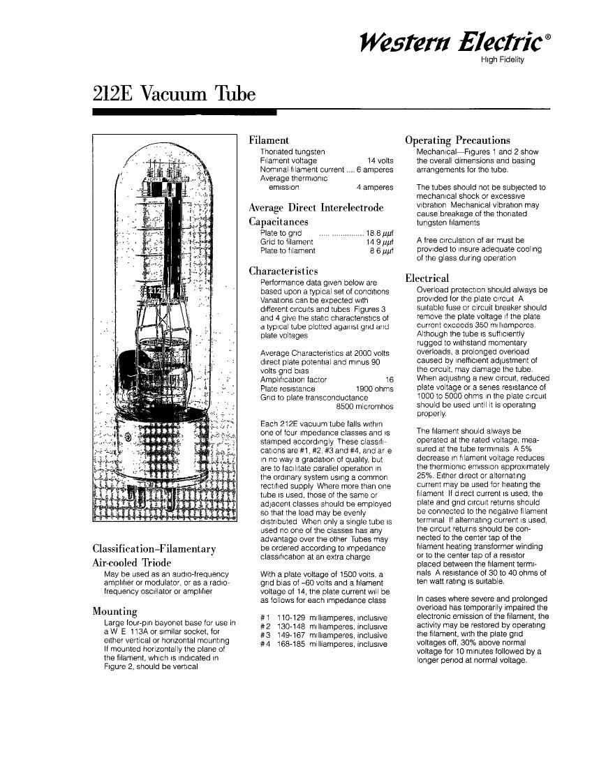
Western electric 212 e brochure
This is the 4 pages manual for western electric 212 e brochure.
Read or download the pdf for free. If you want to contribute, please upload pdfs to audioservicemanuals.wetransfer.com.
Extracted text from western electric 212 e brochure (Ocr-read)
Page 1
Watery £1ecfric®
212E Vacuum Tube
High Fidelity
Filament
Thoriated tungsten
Filament voltage 14 volts
Nominal filament current 6 amperes
Average thermlonic
emisston 4 amperes
Average Direct Interelectrode
Capacitances
Plate to grid llllllllllllllllllll 18,8 turf
Grid to filament 14 9 turf
Plate to filament 8 6 mil
Characteristics
Performance data given below are
based upon a typical set of conditions
Variations can be expected With
different circwts and tubes Figures 3
and 4 give the static characteristics of
a typical tube plotted against grid and
plate voltages
Average Characteristics at 2000 volts
direct plate potential and minus 90
volts grid bias
Amplification factor 16
Plate reststance 1900 ohms
Grid to plate transconductance
8500 micromhos
Each 212E vacuum tube falls Within
one of tour impedance classes and is
stamped accordingly These ClaSSlfh
cations are #1, #2, #3 and #4, and are
in no way a gradation of quality, but
are to labilitate parallel operation in
the ordinary system using a common
rectified supply Where more than one
tube is used. those of the same or
adiacent classes should be employed
so that the load may be evenly
distrlbuted When only a single tube is
used no one of the classes has any
advantage over the other Tubes may
be ordered according to Impedance
classification at an extra charge
Classification-Filamentary
Air-cooled Triode
May be used as an audio»frequency
amplifier or modulator, or as a radio,
frequency oscrllator or amplifier
Mounting
Large four-pln bayonet base for use in
a W E 1 13A or srmilar socket. for
either vertical or horizontal mounting
If mounted horizontally the plane of
the filament, which is Indicated in
Figure 2, should be vertical
With a plate voltage of 1500 volts. a
grid bias of -60 volts and a filament
voltage of 14, the plate current Will be
as follows for each impedance class
#1 110-129 milliamperes, incluswe
#2 130-148 milliamperes,inc|usrve
#3 149-167 milliamperes, inclusive
#4 168485 mllliamperes, inclusive
Operating Precautions
MechanicaliFigures 1 and 2 show
the overall dimensions and basing
arrangements for the tube
The tubes should not be subjected to
mechanical shock or excessive
Vibration Mechanical vibration may
cause breakage of the thoriated
tungsten filaments
A free Circulation of air must be
provtded to insure adequate cooling
of the glass during operation
Electrical
Overload protection should always be
provtded for the plate Circuit A
suitable fuse or circuit breaker should
remove the plate voltage if the plate
current exceeds 350 milliampcros,
Although the tube is sufficiently
rugged to Withstand momentary
overloads, a prolonged overload
caused by ineflictent adiustment of
the Circuit. may damage the tube.
When adiusting a new crrcutt, reduced
plate voltage or a series reelstance of
1000 to 5000 ohms in the plate circuit
should be used until it is operating
properly
The filament should always be
operated at the rated voltage, mea
sured at the tube termlnals A 5%
decrease in filament voltage reduces
the thermionic emISSion appro>
current may be used for heating the
fllament If direct current is used, the
plate and grid cichit returns should
be connected to the negative filament
terminal If alternating current is used,
the Circwt returns should be con-
nected to the center tap of the
filament heating transformer winding
or to the center tap of a reststor
placed between the filament termi-
nals A reSIstance of 30 to 40 ohms of
ten watt rating is surtable.
In cases where severe and prolonged
overload has temporarily impaired the
electronic emission of the filament, the
activity may be restored by operating
the filament, With the plate grid
voltages off, 30% above normal
voltage for 10 minutes followed by a
longer period at normal voltage.
Page 2
212E Vacuum Tube
Operation
Max my- 312 ngs
la .0|tage 3-300 volts
late current .. 350 ml arrpe'es
275 earls
75 ml emperes
_ 5 ampe'es
Max requenr Mrtle abeElEIIIgS 1 5 megaHertz
e fe' Jcoer' c, Ilrnt of 4 5 MHz ts
.vee" 1 5 and 4 5 "fir-l2 r- oroportlor
so lot aop , elm. eously
pecmec ce 3;.
but sec-end on tle type of sen. c
Class A Audio Amplifier or Modulator
D-'e-:t p ate .3 tags EIC
~57
70 230 mu artpe'es
250 250 watts
Load IMpeaence 5300 303 mm;
unalstoned outth 50 40 watts
Grid Bias Modulator
Dlrect slate toltage 3003 vats
Grd b as 263 .O.S
P ate dlss cat on 175 watts
Lea: moedance 8003 ohrrs
Pea< po.-.er CJtht 200 watts
Class B Audio Amplifier or \lodulator for balanced 2 tube circuit
Dl'ec: s-ate .oltage 2033- 1500 '.o|',s
Gr (1 b as ~1C5 -75 volts
Erect slate current per mm No CI.€ £0 50 rt Illamceres
flex :r .e 330 300 .-.-, Illamoeres
P ate 3 55 pa n 25-:- 250 watts
Lea: res at 37p ate OCC- 5903 ohms
LcaC'es 0 2-330 1475 ohrrs
rnax Cutout 65C- 533 sass
rmewced pc- er for air .lrg stage 50 53 -.1.a:s
B Radio-Frequency Amplifier
Clae\o| e 2203 533
300 303
- 275 275
CIaS .120 .92 l
Apoox car 9' 3.21:3 for use All" 103% mcdu- ate" CC- 150 -.
C RadioFrequenryt Oscillator or Power Amplifier-Lnmodulated
2300 1503 velts
360 300 mlllamoeres
G'IC was 7185 to -250 450 to 206 vo-ts
\c-"lra ooaeroutput .. 400 303 watts
Class C Radio-Frequency Amplifier-Plate Modulated
Dl'ect p ate v3 tags 1500 1030 volts
Dl'ect plate cu'rent 303 300 mlllampe'es
Gr d b as .. -203 -125 volts
Ivax alrect grld ou'rent .. , 75 75 rrlllllamperes
Nom nal carrler oowe' output for
use Nth 100% modulation .. 300 200 arts
Dimensions
D mens ms and outllre dlagrarrs e
n Figures 1 and 2 The overal dlme sums
a'e
Maxrnur cvere 9191] 13 5 8'
Maxmun' dla'neter 3 5 8'
Audio Amplifier or Modulator
Class A-Ceak grla' cnve eau ' 1
t'lan me grla bias
Gr-d b as may be obtalred rcrr the 3'3:
across a reelstarce lr me plate Curre-lt
return or for. a reeilf ea supply
Dlate a-ss catlon allows e for thls type 0"
sew as Is gererally Ione' than ls safe c
We uses slrce tre enetg, Is 3 ss pared II"
the plate 'l smal-er a'eas due to relat tely
h-gl" .oltage drop In tl~e tube
The plate dlSSIpallOn ls equal to the olate
vo-taga 'nulllDlled by he normal plate
current. Performance data are cased upon
the use 0" a re5lsta1ce load Urdlstortec
outout ls calculated on the ba5ls 0" 5%
secord Ia'morlc dlstc't 0'1
Class HM 0185 pracllcally at cur~off and
9nd :1eran voltage hlgner man the was
Two tubes may he uses In a balanced
Clrcut A1 adquate arlvmg stage and an
IDdi tratsormer mh good rnglauon us:
be used so tnat tle gr d current draw"
CUIlg pcsmve grld smfigs does rot
produce appreolable dlstortlon ~le output
transformer sz. t'ansfor'n the load
mpeua'lce to he Draper valJe the tubes
used The cave output obtalneole atlll be
cetermlred b, the quallty cf tlte transforme'
used and he arount of o slort 0'1 alt C can
be tolerated T'1e grld b as must be field
onstant and theretore ca'1r3t be obianed
b; gr d leak or ser es 'eSISt-Clr met'lods A
restfes d c supply (2' otner source EV ng
good regulatlon ls recesse'y
The poser 'equ 'ed of e POdJlaZC' 3:
com ete 'nocu'atlon of a Case C ampllle'
ls or all the c rect power nput to the
DI: s of t'le Class C an) le'