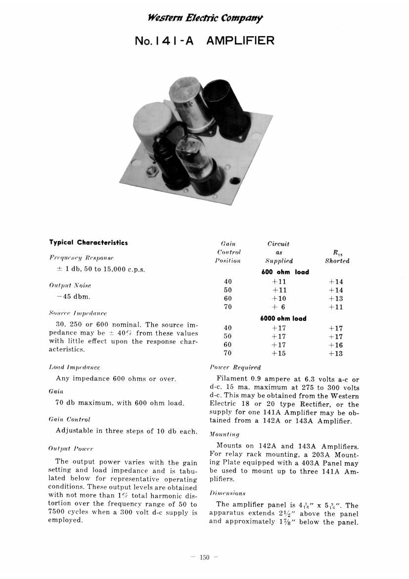
Western electric 141 a schematic
This is the 2 pages manual for western electric 141 a schematic.
Read or download the pdf for free. If you want to contribute, please upload pdfs to audioservicemanuals.wetransfer.com.
Extracted text from western electric 141 a schematic (Ocr-read)
Page 1
Willem Electric Company
No. | 4 | -A AMPLIFIER
Typical Characteristics
Frr'qm-m'y Iumponxr'
i 1 db, 50 to 15.000 c.p.s.
Our/m! Noise
+45 dbm.
Sum'm' Impmlnnm'
30, 250 or 600 nominal. The source im»
pedance may be : 40] from these values
with little effect upon the response char-
acteristics.
Loud Impmlnncc
Any impedance 600 ohms or over.
Gain
70 db maximum, with 600 ohm load.
Gain Control
Adjustable in three steps of 10 db each.
Output Iou'v'r
The output power varies with the gain
setting and load impedance and is tabu»
lated below for representative operating
conditions. These output levels are obtained
with not more than 1?} total harmonic dis-
tortion over the frequency range of 50 to
7500 cycles when a 300 volt d»c supply is
employed.
Gain Circuit
Control as It,5
Position Supplied Shorted
600 ohm load
40 +11 +14
50 +11 +14
60 +10 +13
70 + 6 +11
6000 ohm load
40 +17 +17
50 +17 +17
60 +17 +16
70 +15 +13
Po ircr Required
Filament 0.9 ampere at 6.3 volts a-c or
d-c. 15 ma. maximum at 275 to 300 volts
d-c. This may be obtained from the Western
Electric 18 or 20 type Rectifier, or the
supply for one 141A Amplifier may be ob-
tained from a 142A or 143A Amplifier.
Mounting
Mounts on 142A and 143A Amplifiers.
For relay rack mounting. a 203A Mount-
ing Plate equipped with a 403A Panel may
be used to mount up to three 141A Am-
plifiers.
Dimensions
The amplifier panel is 4,7,, x 51.;"i The
apparatus extends 2% above the panel
and approximately 17/3 below the panel.
150