Western electric 131 a schematic
This is the 2 pages manual for western electric 131 a schematic.
Read or download the pdf for free. If you want to contribute, please upload pdfs to audioservicemanuals.wetransfer.com.
Extracted text from western electric 131 a schematic (Ocr-read)
Page 1
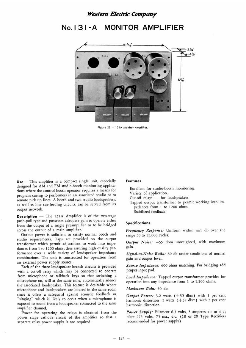
Western Electric Company
No. | 3| -A MONITOR AMPLIFIER
lolis'
Figure 23 7 I3lA Monilor Amplifier.
Use-This amplifier is a compact single unit, especially
designed for AM and FM studio-booth monitoring applica-
tions where the control booth operator requires a means for
program cueing to performers in an associated studio or to
remote pick up lines. A booth and two studio loudspeakers,
as well as line cue-feeding circuits, can be served from its
output network.
Description - The 131A Amplifier is of the two-stage
push-pull type and possesses adequate gain to operate either
from the output of a single preamplifier or to be bridged
across the output of a main amplifier,
Output power is sufficient to satisfy normal booth and
studio requirements. Taps are provided on the output
transformer which permit adjustment to work into impea
dances from 1 to 1200 ohms, thus assuring high quality per-
formance over a wide variety of loudspeaker impedance
combinations, The unit is constructed for operation from
an external power supply source.
Each of the three loudspeaker branch circuits is provided
with a cut-off relay which may be connected to operate
from microphone or talkback keys so that switching a
microphone on, will at the same time, automatically silence
the associated loudspeaker. This feature is desirable where
microphone and loudspeakers are located in the same room
since it offers a safeguard against acoustic feedback or
"singing" which is likely to occur when a microphone is
exposed to sound from a loudspeaker connected to the same
amplifier channel.
Power for operating the relays is obtained from the
power stage cathode circuit of the amplifier so that a
separate relay power supply is not required.
Features
Excellent for studio-booth monitoring.
Variety of application.
Cut-0H relays i for loudspeakers.
Tapped output transformer to permit working into im-
pedances from 1 to 1200 ohms.
Stabilized feedback.
Speciflculions
Frequency Response: Uniform within :1 db over the
range 50 to 15,000 cycles.
Output Noise: -55 dbm unweighted, with maximum
gain.
Signal-ta-Noire Ratio: 80 db under conditions of normal
gain and output level.
Source Impedance: 600 ohms matching. For bridging add
proper input pad.
Load Impedance: Tapped output transformer provides for
operation into any impedance from 1 to 1,200 ohms.
Maximum Gain: 50 db.
Output Power: 3.2 watts (+35 dbm) with 1 per cent
harmonic distortion; 5 watts (+37 dbm) with 5 per cent
harmonic distortion.
Power Supply: Filament 6.3 volts, 3 amperes a-c or d-c;
plate 275 volts, 7S ma, do (18 or 20 Type Rectifiers
recommended for power supply).
*1427