Western electric 130 b schematic
This is the 2 pages manual for western electric 130 b schematic.
Read or download the pdf for free. If you want to contribute, please upload pdfs to audioservicemanuals.wetransfer.com.
Extracted text from western electric 130 b schematic (Ocr-read)
Page 1
Wee-mm Electric Company
No.|30-B TWIN CHANNEL MAIN AMPLIFIER
I ,
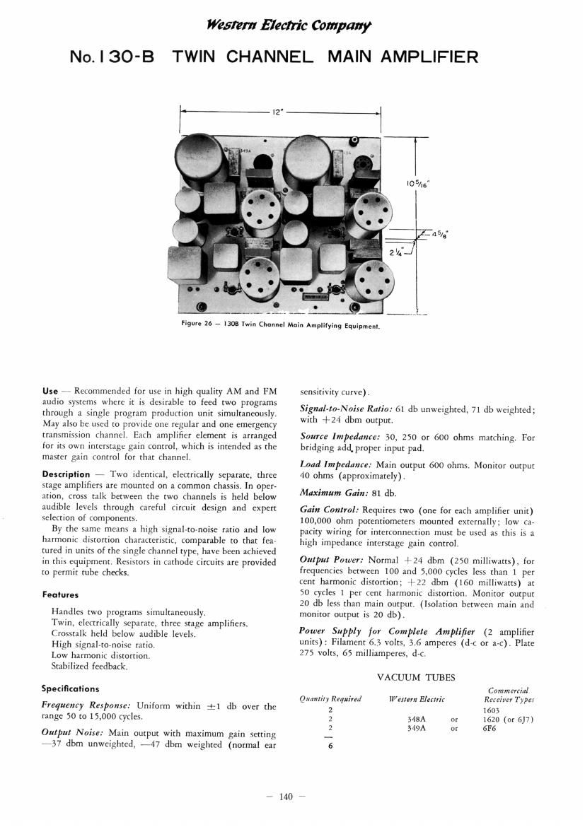
Figure 26 ~ 1303 Twin Channel Main Amplilying Equipmenl.
Use 77 Recommended for use in high quality AM and FM
audio systems where it is desirable to feed two programs
through a single program production unit simultaneously.
May also be used to provide one regular and one emergency
transmission channel. Each amplifier element is arranged
for its own interstage gain control, which is intended as the
master gain control for that channel.
Description - Two identical, electrically separate, three
Stage amplifiers are mounted on a common chassis, In oper-
ation, cross talk between the two Channels is held below
audible levels through careful circuit design and expert
seleCtion of components.
By the same means a high signalrto-noise ratio and low
harmonic distortion characteristic, comparable to that fear
tured in units of the single channel type, have been achieved
in this equipment. Resistors in cathode circuits are provided
to permit tube checks.
Feaiures
Handles two programs simultaneously.
Twin, electrically separate, three stage amplifiers.
Crosstalk held below audible levels.
High signal-to-noise ratio.
Low harmonic distortion.
Stabilized feedback.
Specifications
Frequency Response: Uniform within :1 db over the
range 50 to 15,000 cycles.
Output Noise: Main output with maximum gain setting
*37 dbm unweighted, #47 dbm weighted (normal ear
- 140
sensitivity curve).
Signol-lo-Noise Ratio: 61 db unweighted, 71 db weighted;
with +24 dbm output.
Source Impedance: 30, 250 or 600 ohms matching. For
bridging add proper input pad.
Load Impedance: Main output 600 ohms, Monitor output
40 ohms (approximately),
Maximum Gain: 81 db.
Gain Control: Requires two (one for each amplifier unit)
100,000 ohm potentiometers mounted externally; low ca-
pacity wiring for interconnection must be used as this is a
high impedance interstage gain control.
Output Power: Normal 4-24 dbm (250 milliwatts), for
frequencies between 100 and 5,000 cycles less than 1 per
cent harmonic distortion; +22 dbm (160 milliwatts) at
50 cycles 1 per cent harmonic distortion. Monitor output
20 db less than main output. (Isolation between main and
monitor output is 20 db).
Power Supply for Complete Amplifier (2 amplifier
VACUUM TUBES
Commercial
mi NNN
units): Filament 6.3 volts, 3.6 amperes (d-c or a»c). Plate
275 volts, 65 milliamperes, d
Qmmri/y Required Wet/em Electrir Receiver Type;
1603
MBA or 1620 (or 6J7)
549A or 6F6