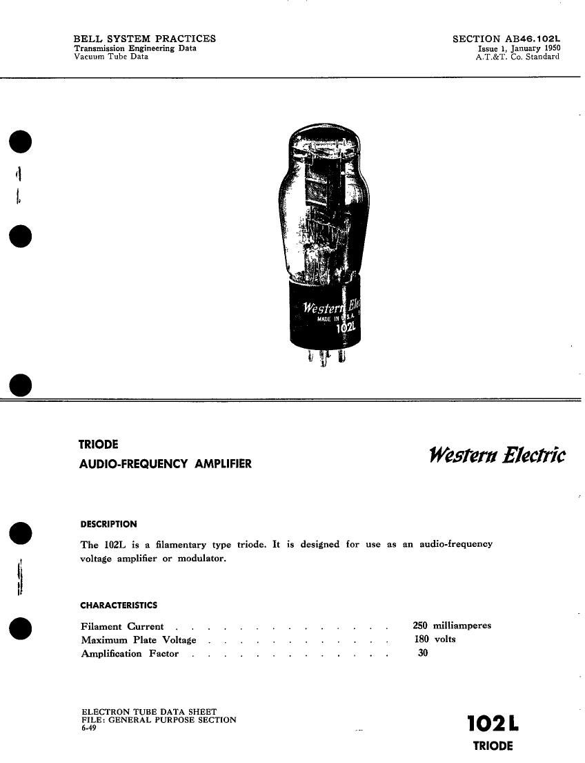
Western electric 102 l brochure
This is the 6 pages manual for western electric 102 l brochure.
Read or download the pdf for free. If you want to contribute, please upload pdfs to audioservicemanuals.wetransfer.com.
Extracted text from western electric 102 l brochure (Ocr-read)
Page 1
BELL SYSTEM PRACTICES SECTION AB46.102L
Transmission Engineering Data Issue 1, January 1950
Vacuum Tube Data A.T.&T. Co. Standard
TRIODE .
AUDIO-FREQUENCY AMPLIFIER WSW! 51961776
DESCRIPTION
The 102L is a filamentary type triode. It is designed for use as an audio-frequency
voltage amplifier or modulator.
CHARACTERISTICS
Filament Current . . . . . . . . . . . . . . 250 milliamperes
Maximum Plate Voltage . . . . . . . . . . . . 180 volts
Amplification Factor . I . . . i . . . . , . . 30
ELECTRON TUBE DATA SHEET
135E: GENERAL PURPOSE SECTION 102 '-
'I'RIODE
Page 2
'IO2L -- PAGE 2
GENERAL CHARACTERISTICS
ELECTRICAL DATA
Filament Current , , , . , , . _ . V _ . . . . 250 milliamperes
Filament Voltage. Nominalé . , . . . . . . . . . . , 2.1 volts
Direct Interelectrode Capacitances without external
shield
Grid to Plate . . . . . . . . . . . . . . . . 5.0 uuf
Input . . . , . . . . . . . . . . . . . . 3.8 uuf
Output , . . , . . . . . . . . . . . . 2.4 not
MECHANICAL DATA
Cathode . . . , . . . . . . . . . . . . . Coated Filament
Base . . . . . . . . i . , , lVIedium 4-pin type with bayonet pin
Mounting Position. . . . . . . . . Preferably vertical; if horizontal, pins #1
and #2 must lie in same vertical plane
Dimensions and pin connections shown in outline drawing on Page 5
MAXIMUM RATINGS, Design-Center Values
Plate Voltage . . . . . . . . . . . . . . . . 180 volts
Plate Dissipation . . . . . . i . . . . . . . . . 0.5 watt
Plate Current . . . . . . . . . . . . . . . . . 7.5 milliamperes
TYPICAL OPERATING CONDITIONS AND CHARACTERISTICS-CLASS AI AMPLIFIER
Filament Current, D-C . . . . . . . . . 250 250 milliamperes
Plate Voltage . . . . . . . . . . . . . 130 160 volts
Grid Voltage . . . . . . . . . . . . . -1.5 -2.0 volts
Peak A-F Grid Voltag . . . . . . . . . . 1.5 2.0 volts
Plate Current . . . . . . . . . . . . . 0.85 1.2 milliamperes
Transconductance . . . , . . . . . . . . 650 800 micromhos
Amplification Factor . . . . . . . . . . . 30.2 30.2
Plate Resistance , . . . . . . . . . . . 46000 39000 ohms
Load Resistance . . . . . . . . . . . . 300000 300000 ohms
NIaximum-Signal Voltage Output . , . . . . . 34 44 peak volts
Total Harmonic Distortion Less Than . . . . . . 1.0 1.0 per cent
*The filament resistance of this tube increases slightly during the first year of operating life.
The voltage given above is the nominal value after the filament resistance has stabilized.