Toshiba PC X88AD Service Manual

This is the 35 pages manual for Toshiba PC X88AD Service Manual.
Read or download the pdf for free. If you want to contribute, please upload pdfs to audioservicemanuals.wetransfer.com.

Page: 1 / 35
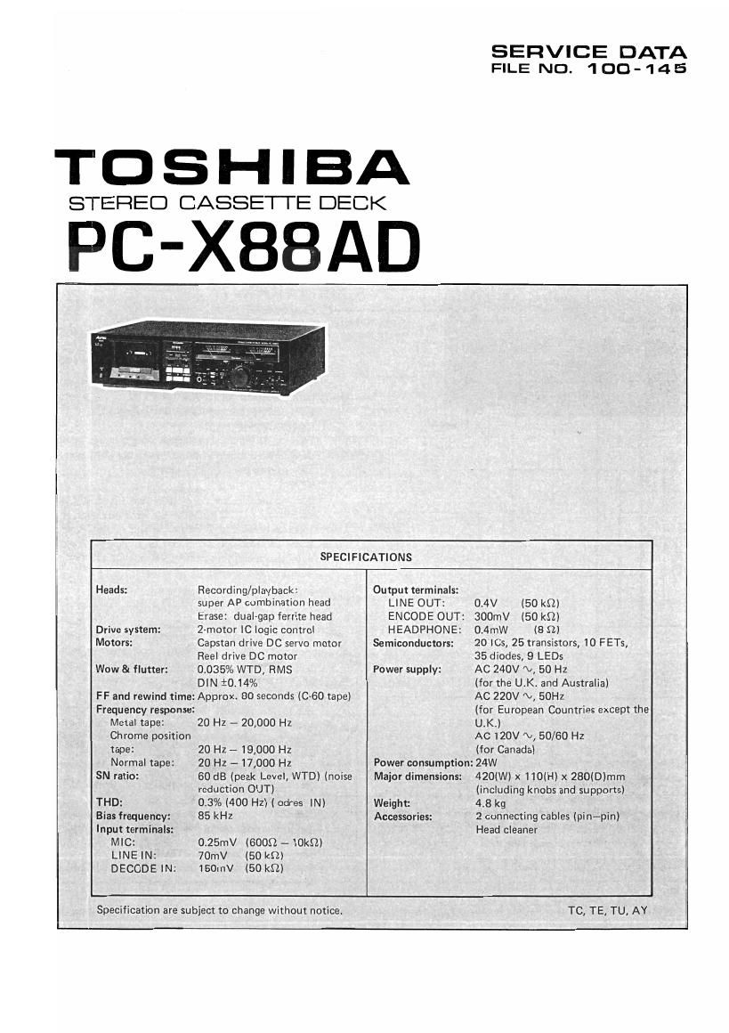
Toshiba PC X88AD Service Manual

Extracted text from Toshiba PC X88AD Service Manual (Ocr-read)


Page 1

SERVICE DATA
FILE NO. 100-145

TOSHIBA

STEREO CASSETTE DECK

PC-XBBAD

SPECIFICATIONS
Heads: Recording/playback: Output terminals:
super AP combination head LINE OUT: 0.4V (50 k9)
Erase: dual-gap ferrite head ENCODE OUT: 300mV (50 k9)
Drive system: 2-motor IC logic control HEADPHONE: 0.4mW (8 S2)
Motors: Capstan drive DC servo motor Semiconductors: 20 ICs, 25 transistors, 10 FETs,
Reel drive DC motor 35 diodes, 9 LEDs
Wow & flutter: 0.035% WTD, RMS Power supply: AC 240V N, 50 Hz
DIN 10.14% (for the UK. and Australia)
FF and rewind time: Approx. 80 seconds (C-60 tape) AC 220V N, 50H:
Frequency response: (for European Countries except the
Metal tape: 20 Hz w 20,000 Hz U.K.)
Chrome position AC 120V V, 50/50 Hz
tape: 20 Hz - 19,000 HZ (for Canada)
Normal tape: 20 Hz - 17,000 Hz Power consumption: 24W
SN ratio: 60 dB (peak Level, WTD) (noise Major dimensions: 420(W) x 110(H) x 280(D)mm
reduction OUT) (including knobs and supports)
THD: 0.3% (400 Hz) (cdres IN) Weight: 4.8 kg
Bias frequency: 85 kHz Accessories: 2 connecting cables (pin-pin)
Input terminals: Head cleaner
MIC: 0.25mV (6009. - lOkQ)
LINE IN: 70mV (50 kn)
DECODE IN: 150mV (50 kS'l)

Specification are subject to change without notice. TC, TE, TU, AY

Page 2

PC-X88AD l

CONTENTS


1. FEATURES .............................................................. 2
2. SYSTEM CONNECTIONS ................................................... 4

3. OPERATING INSTRUCTIONS ....... . . 5to 10

4. TECHNICAL POINT .................................................... 11 to 12

5. DISASSEMBLY INSTRUCTIONS ........................................... 13to 19

6. BLOCKDIAGRAM .................. 20
7. ELECTRICAL ADJUSTMENTS ............................................ 21 to 22

8. ELECTRICAL PARTS LOCATIONS (MAIN) ....................................... 23

9. SCHEMATIC DIAGRAM (MAIN) ............................................... 24
10. ELECTRICAL PARTS LOCATIONS(ADRES/MUT|NG) ................................ 25
11. SCHEMATIC DIAGRAM (ADRES) .............................................. 26
12. WIRING DIAGRAM ........................................................ 27
13-1. EXPLODED VIEW (MECHANISM) .............................................. 28
132. EXPLODED VIEW (MECHANISM) PARTS LIST ..... 29
14-1. EXPLODED VIEW (CABINET) ................................. 30
14-2. EXPLODED VIEW (CABINET) PARTS LIST ....................................... 31
15. PARTS LIST ......................................................... 32 to 37

oo@

Noise Reduction System is manufactured under license from Dolby Laboratories.
"DOLBY" and the Double-D symbol are Trademarks of Dolby Laboratories Inc.

OdreS is the new noise-reduction and Automatic Dynamic Range Expansion System developed by TOSHIBA

Corp., Tokyo, Japan

LFEATURES

0 Three-head deck with recently developed combination record/playback head
The new super AP head developed by TOSHIBA features a unique tapered head shape to ensure that the
recording head makes perfect head-to-tape contact for optimum recording performance.

0 Dual odres system for maximum quality of sound
The 4-channel adres circuit in this deck anables recordings to be monitored during the recording operation.

4-channel odres unit for expanded cdres capacity

When connected to another tape deck, odres recording and playback in the other deck is also possible.

High-performance 2-motor IC logic mechanism

Memory counter and auto repeat functions

Adjustable recording and playback sensitivity

Fine adjustment of recording bias

Tape transport mode buttons with built-in indicator lamps
Remote control unit connector terminal

Recording mute for easier editing

Sl
Iv
19

19
19
es

:h
)n

rr)

Page 3

(D Tape Counter [TAPE COUNTER] k

PCX88AD PC~X88AD

2. OPERATING CONTROLS

® Timer Standby Switch [TIMER]

@ Memory Switch [MEMORY]

For setting unattended recording and playback with a
timer. Also used for automatic repetition playback,
During normal operation, leave in the OFF position.
(See pages (9) and (10) for details.)

® Tape Window Lamp

For automatlc tape start search and automatic repeti-
tion playback, (See page (26) for details.)

(WT-

@ Cassette Compartment Door

@ Power Switch [POWER]
@ Eject Button [ A EJECT]
® Play button [b]

If the pause button [ ll ] ® is pressed, the play

button builtrin lamp turns off, and the deck put into
playback standby mode.

Rewind Button [44]

® Record Button [O REC]
Recording mode is started when this button is pressed
together with the play button [b ] ®

If the pause button [ ll ] @l is pressed, the play

button builtin lamp turns off, and the deck put into
recording standby mode,

® Stop Button [ I ]

® Pause/Record Mute [ll/o MUTE]

For temporary stop of tape transport, and prepara-
tion of blank sections of tape during recording mode.
(See page (7) for details.)

@ Fast Forward Button [>>]

® Headphones Jack [PHONES]

Tape Selector [TAPE]

® Noise Reduction Switch [NR]

® Recording Bias Fine Adjustment [BIAS FINE]
For tine adjustment of optimum recording bias for
the tape to be used for recording purposes. (See page
(8) for details.)

WEE ll '51. lI
minim/m

Figure1

DUPL] . .
< MONI > Duplicate/monitor

Use this position for simultaneous playback monitor-
ing and dubbing of an odres encoded tape,

< m >

Use this position for Odfes recording and playback.
(See page (5) and (6) for details.)

Set to this position when the noise reduction system
is not being used.

® Playback Deck Selector [PB/CAL]
< EXT

DECK /CAL> External deck
Set to this position when using another tape de:k.
(See page (6) for details.)
<|NT DECK>
Set to this position when using the PC»X88AD tape
deck.
<|NT DECK~ADJ>

(See page (7) and (8) for details.)

® 66;: Calibration Controls [[5335] CAL]
Used in adjusting the adres reference level in other
tape decks. These controls are not required for re-
cording and playback in the PC-X88AD. (See page
(6) for details.)

-@ Indicator Lamps

-@ Set Level Marker

® Level Meters

® Recording Level Sensitivity Adjustment Controls
[SENS (RECH
For adjusting the correct recording level. (See page
(7) for details.)

@ Monitor Switch [MONITOR]
For selecting the monitor (output) signal.

For monitoring the input signal being recorded by the
deck. Also set to this position when the [NR] switch
@ is set to the < R/Ifijphlfil > position.

For monitoring the signal (playback signal) just re-
corded by the PC-XSSAD. By switching back and
forth between the and posi-
tions, the recorded signal can be compared directly
with the source program (simultaneous monitoring
during recording mode).

® Input Selector Switch [INPUT]
For selecting the tape deck input signal.
Internal oscillator
Set to this position when adjusting the recording
sensitivity for the PC-X88AD, and when recording
with odres in the external tape deck. (See pages
(6) for details.)

@ Input Level Adjustment Control [INPUT LEVEL]
For adjusting the input level. The outer ring is for
the right channel, and the centre control for the left
channel. (See page (7) for recording level adjust-
ment details.)

Set to this position for recording from phonograph
records and other tapes. Also set to this position
when the [NR] switch ® is set to the digit >
position.

Set to this position (or recording FM stereo and TV
multiplex broadcasts.

Set to this position (or live microphone recordings.

_® Output Level Control [OUTPUT]
For adjustment of the tape deck output (monitor)
level and headphones output level.

Page 10

PC-X88 Al:

I NR Recording of a Non-Encoded Tape

(D Play the non-encoded tape in the external tape deck. 0 The recording can be monitored during the dubbing process
Note: Make sure that the amplifier FUNCTION selector is in the by switching the amplifier tape monitor 5W|tch to the
AUX position. TAPE position.

® Set the PC-X88AD [NR] switch to the desired noise reduc- Note: Set the PC-XSSAD monitor switch to the position,
tion system, and proceed to record the playback signal.
Note: Set the input selector switch to the position.

Automatic Tape Start Search and Playback

Set the tape counter to <000> at the position where you wish The [MEMORY] switch and [TIMER] switch may be used in
the tape to start from again later on. When the tape is rewound combination in a number of ways for different automatic
afterwards, tape transport will stop automatically at <999>, operational modes (see accompanying chart).

and resume playback in repeat mode (if so set).

F - TAPE COUNTER Switch
unctlon
W Tape start <999> Tape end TIMER MEMORY
| I |
l REW
H-<<-
Memory , 'STOP i : OFF STOP
stop I l ,
: . . , -a
I | l l
1 I i new
l
Memory PLAY 1 OFF PLAY
i i l > : ,
l i 1 i
PLAY
Autp- l i i
rewind l i i emf": new OFF
stop 15TOP I <1 i
l l I |
k Auto i : PLAY 1'
- l
rewmd l i i ->-fl' HEW STOP
mm = l ' =: m 4: .
stop I STOP ' l
I l I
i . i i
'i i I PLAY i
l 'i l 4 Raw 44 i
. i VV |
Memory l L l _ PLAY _
repeat 1 i , V r ]
i i 1< REW =4 . new PLAY
; i 1 PLAY_, _ Repeat 1
l l l l
M ' d F Figure 18
a [or O res eatu res

- odres (Automatic Dynamic Range Expansion System) is a emphasis circuit, there is very little breathing" phenome-
major breakthrough (SUCCESSfUUY achieved bY TOSH'EA non, In other words, the odres system is the right type of
engineers) in the elimination of hiss noise inherent to tape. noise reduction system for cassene tape decks.

(This noise is the result of the tape being narrow and moving Typica| odresnemiu
slowly.)

I odres contains a variable emphasis circuit designed to vary
the emphasis characteristics according to the input signal
level. By compression before recording and expansion during
playback of the signal right across the complete frequency
spectrum, a clear, powerful playback signal may be obtained
with a greatly expanded dynamic range and vastly improved
SN ratio.

0 Because of the effective value detector system in the odres
level sensor circuit, there is practically no mis-matching due
to differences in tape and tape deck characteristics. Further-
more, slight mismatching between input and output levels
does not result in a significant change in sound quality.

0 Furthermore, by keeping the compression/expansion ratio m mm m
to a power of almost 1.5, and by incorporating the variable Fr-w'rWWl

710_ Figure 19

Output lell Ida)

m

Page 12

PC-X88A

3. Disconnect six joint wires (H), 7p connector and 4p
connector on P.C. Board, then panel assembly can be
removed frontwards.

4. Remove two screws (I) holding Main P.C. Board,
then remove meter P.C. Board and peak meter from
the front panel.

CAUTION:
When disconnecting joint wires, confirm the position
as it is.

5. Remove one screw (J) (3o x 6mm) on the inside of
the MIC jack from the main chassis, then the shield
plate can be removed.

6. Disconnect two cord cramps (K) on Main P.C. Board
to release the cords.

E (M) (13¢ x 8mm)
' ? (J) (3o x 6mm)

ADRES P.C. BOARD AND MUTING P.C. BOARD REMOVAL
1. Remove two screws (L) (3o x 8mm) holding ADRES
P.C. Board. (L) ?
2. Remove two screws (M) (34¢ x 8mm) holding Muting (3¢ x 6mm)
P.C. Board.

MECHANISM ASSEMBLY REMOVAL
1. Remove the front panel (Refertofront panel removal).
2. Remove three red screws (N) (341) x 8mm) holding
mechanism assy and one red screw (0) (3d) x 8mm)
holding cord cramp. (K)
CAUTION:
When removing Mechanism Assy from the front
panel, confirm the installation position of counter
belt.

Figure 28

gonzo x 8mm) ?(0) W X 3mm,
? (I) (3d: 12mm)

TAPE COUNTER REMOVAL
1. Remove two screws (P) (2.645 x 8mm) on the front
panel, then tape counter can be removed out:

KEY SWITCH REMOVAL g (0) (26¢ x 8mm)

1. Remove two screws (0) (2.64) x 8mm) holding key % (N) (3¢x 8mm)
switch P.C. Board, then key switch and LED. holder
can be removed from the front panel. Figure 29

_12_