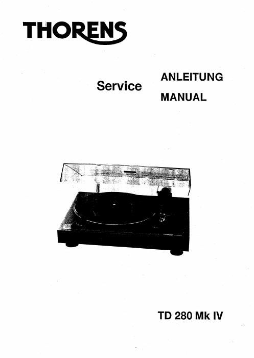
Thorens td 280 mk4 service manual

This is the 8 pages manual for thorens td 280 mk4 service manual.
Read or download the pdf for free. If you want to contribute, please mail your pdfs to info@audioservicemanuals.com.

Page: 1 / 8
left right
thorens td 280 mk4 service manual

Extracted text from thorens td 280 mk4 service manual (Ocr-read)


Page 2

THORENS-Ptattenspieler TD 280 Mk [V

Der THORENS-Plattenspieler TD 280 Mk IV hat einen
ZweiphasewSynchronrnotor mit 24 Magnetpolen. Dieser weist so
geringe Emehutterungen auf, saB man mil ihm aut das tur andere
THORENS-Plattenspieler typische Subchassis vsrzichten kann
und dennoch einen Rumpelgereuechspannungsabstand von mehr
als 70 dB erziett. Mit dieser MaBnahme steht ein preisgfinatiger
Plattenepieler zur Vertugung. der auch unter schwingtechnisch
ungunstigen Verhaltnissen, wie sie etwa irn Allbauten mit
biegeweichen HolztuBboden anzutreffen sind, gegen Trittschall
weilgehend unempfindlich ist.

Plattenteller und Motorlager

Das Plattentellerlager brancht erst nach ca. 1000 Betriebsetunden
odor nach lingerem Stfllstand nadigetettet warden. be as sidt bei
diesern Lager urn eine selbstzenlrierende hangende Konstruktion
handelt. dart keln OI verwendet warden!

Des alto Fett wird mit einem Watteslébohen flusenirei enttemL Des
THORENS-BOW-lnstrurnententdt wird dam in die Lagerbuchse
gedruckt. Beim Auisetzen dee lnnentellers aut die Achse
unbedingt auf einwandfreie Lage der Kugel achtenl

Tonarrnausbau

Die Bodenplatte entiernen. Sie ist mit sechs Schrauben betestigt.
An der Ruckwand des Gehauses ist die Nelzbuchse und die NF-
Loihung betestigt. Schraube an der Lichtblende losen und nach
leichter Rechtsdrehung abziehen. Die hint Tonarrnleitungen an der
Endabschaltungsplatine und die Magnetzuleitung abléten. Das
Kupplungsetuck der Schaltstangen losen und diese am Tonarm
aushangen. Die drei Tonarm-Betestigungsschrauben enttemen
und die Tonarmeinheit nach oben abheben.

Tonarmeinbau

Der Einbau des Tonarrnes erfolgt in umgekehrter Reihentolge zum
Ausbau. Schalblende autsetzen und in den Optokoppter
einiflhren. Sie mufi so justiert werden, daB die gerade Kante der
Blends 1 bis 1,5 mm aus der Lichtschranke ubersteht und mit der
AuBenkante des Lichtschrankengehauses liuchtet (Bild 1). Vor
dem Festschraubon der Schaltblende ist drauf zu achten, das sis
in der Mitts der Lichtechrankengabel trei beweglich ist (Enslellmafl
= 5 mm van Leiterplatte bis Unterkante Schaltblende).

Die hint Tonarmlitzen wieder an die Steddétésen gelotet
(Fleihenfolge: gn, rt, maese. we. bl).

Zum ebktrischen Abgleich wird das Gerét
eingeschaltet und am Testpunkt 2 und '3 sin
Glebhepannungs-Meflgerat angeschloseen. Der
Tonarrn wird ganz zur Plattenmitte an den Ansohleg
geschwenkt. Mit dem Potentiometer P3 sirrd nun 0,5 V
einzustellen. Befindet sich der Tonarm in seiner
Haste. so sind ca. 4,7V zu memen.

Tonamrlift

Die Liltbank wird so eingestellt. daB sich die
Nadelspilze in angehobenem Zustand 5 mm fiber der
Plattenoberfléche befindet. Dazu wird die
Madenschraube in der Liflbank oben verstellt.

iC/m\

Bild / Figure 1

THORENSPTurntabIe TD 280 Mk IV

The THORENS TD 280 Mk IV tumtable is driven by a twophase
24-pole synchronous motor. Its vibration level is so low that it
made the use of a suspended chassis unnecessary - a teature
otherwise typical for THORENS-tumtables - and yet the weighted
mmble exceeds 70 dB.

With these steps a reasonable turntable stands at your desposel,
that is insensitive to swingtechnical disadvantageous
circumstances (like old wooden floors in house etc.)

Platter and motor bearing

The beefing of the platter needs to be greased only after appr.
300 working hours or extreme long time without opetation. Since
you deal with abearing that is constructed in a sell-centered
hanging position, no all Is allowed to be used!

The old grease (fat) has to be removed with a coltorrbud. The
Thorens-BOW-Grease is then basing pressed into the
bearingsocket. When putting the innerpletter onto the spindle,
please pay attention to the correct position of the ball!

Tonearm removal

Remove the bottom cover, which is mounted with six screws. The
power socket and the tone arm leads are inserted through the rear
panel.

Loosen screw at the aperture and detach it after a light turn to be
right. Solder off the magnet-leads and the live tonearmleads at the
auto-shut-otf circuit board. Loosen the coupling at the operating
poles, and withdraw them at the tonearm. Remove the tonearm
after loosening the three screws that fasten the arm.

Tonearm installation

Installing the tonearm follows the opposite procedure of
dismanleling it. Attach apeture and move it undemeath the LED.
Adjust the aperture so that its straight edge has an overhang of
about t to 1,5 mm towards the LED and flushes with the outer
edge of the LED'S housing (see figure 1). Before fastening the
aperture. make sure lhet it moves freely underneath the center of
the LED. (It measures 5 mm from circuit-board to the lower edge of
the aperture). Solder the lit-wires into the respective eyes on the
soldering-bar, i.e. in the following order: green. red. ground, white,
blue. In order to accomplish an electrical adjustment for the
automatic litt-oft/shut-off. switch on power and connect
a DC measuring instrument to testing-point 2 and 3
(please reler to circuit diagram). Move. the torrearm
towards the center of the platter until it stops. Using
potentiometer R 102. adjust 0,5 V in this arm position.
if the tonearm is in its armrest, you should then read
m. 4.7 V.

Tonearm lift

The tonearm platform should be adjusted so that the
stylus tip hovers 5 mm (about 1/4 in.) above the
surface of the record. Therelore adjust the grub screw
inside the liftbench.