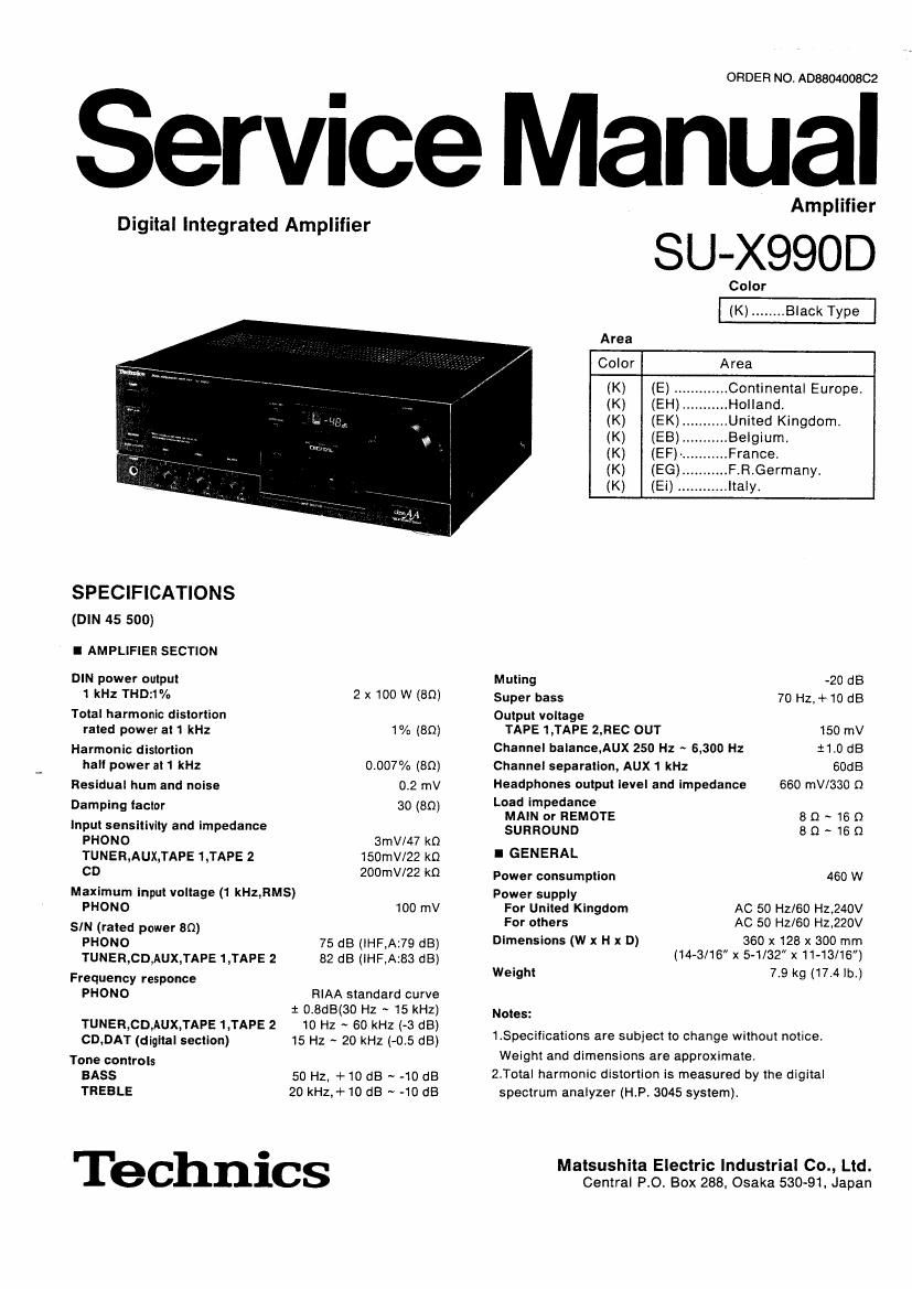
Technics SUX 990 D Service Manual

This is the 25 pages manual for Technics SUX 990 D Service Manual.
Read or download the pdf for free. If you want to contribute, please upload pdfs to audioservicemanuals.wetransfer.com.

Page: 1 / 25
Technics SUX 990 D Service Manual

Extracted text from Technics SUX 990 D Service Manual (Ocr-read)


Page 2

X990D

I CONTENTS


TERMINAL GUIDE OF ICSI
BEFORE REPAIR .................................................... ...2 TRANSISTORS AND DIODES
PROTECTION CIRCUITRY 2 PRlNTER CIRCUIT BOARDS

ACCESSORY .................... 2 WIRING CONNECTION DIAGRAM. 23
LOCATION OF CONTROLS. BLOCK DIAGRAM .......................... 24 ~ 26
CONNECTIONS MEASUREMENTS AND ADJUSTMENTS .I

ALS 7 EXPLODED VIEW .................
' """" REPLACEMENT PARTS LIST ..
FUNCTIONS OF IC TERMINALS..
RESISTORS AND CAPACITORS .

DIGITALIZATION
DISASSEMBLY INSTRUCTIONS.
SCHEMATIC DIAGRAM ..........

I BEFORE REPAIR

(1)Turn off the power supply Using a 100. SW resistor connect both ends of power supply
capacitorstC701,C702,6800uF) in order to discharge the voltage.

(2)Before turning the power supply on , after completion of repair , slowly apply the primary voltage by using
a power supply voltage controller to make sure that the consumed current at 50Hz/60Hz in N0 SIGNAL mode
should be shown below with respect to supply voltage 220V/240V.

Power supply voltage A0220V A0240V
Consumed current 50H: 165 ~ 495mA 152 ~ 456mA
Consumed current 60Hz 158 ~ 474mA 146 ~ 437mA

I PROTECTION CIRCUITRY

The protection circuitry may have operated if either of the following conditions is noticed:
* No sound is heard when the power is switched ON.
* Sound stops during a performance.
The tunction Of this circuitry is to prevent Circuitry damage if, for example, the positive and negative speaker
connection wires are shorted , or it speaker systems with an impedance less than the indicated rated
impedance of this unit are used
If this occurs, follow the procedure outlined below:
l.Switch OFF the power.
2.Determine the cause of the problem and correct it.
3.8witch ON the power once again
Note:
When the protection circuitry functions, the unit will not operate unless the power is first switched OFF and then
0N again

I ACCESSORY

IAC power supply cord ....................................... 1
Configuration of AC power supply cord differs according to
areas

For (E),(EG).(EF),(EH),(EB) and (Ei) areas.
For (EK) area only.

Page 4

su 990D su- 9900

2. Make the connections at the flat cables and the AC power supply cords.

1. Do not connect video-related equipment (such as a TV, etc) to the AC outlets ol these components. (These outlets are especially for audio
equipment.) Also do not exceed the indicated power ratings when connecting to these Outlets.

2, The tuners power outlet is interlocked with the power STANDBY d) ION" switch of the tuner,

3. II the graphic equalizer is not used in combination with these components, connect the AC power supply cord of the compact disc player
to the AC outlet of the amplifier. It the compact disc player is not used in combination with these components, connect the AC power
supply cord at the cassette tape deck to the AC outlet 01 the graphic equalizer.

Note: The configurations of the AC outlets and AC power supply cords difler according to area.

(SL-Jsoon)
Turntable (option)

L_l I_l
/ AC power supply cord
(Included with turntable)
(ST-XSSOL)
Tuner (option) CONTROL Ac OUTLET Household AC 091
AMPLIFIER
<3- @---c\ -@
AC power supply cord
L_J (Included with tuner)

3-core flat cable

NAC IN
I__J
AC power supply cord\ Note:
(Included Wih tuner) (Included with this unit) Connect this cord only after all other
cables and cords have been

(su-xosoo)
""" connected.
This unit
Ac OUTLET
O OE
~Ac IN
CONTROL
El -
I_.I | I_J
LR 8Acore flat cable
(Included with
cassette tape deck)
(SH-E75)
Graphic equalizer AC OUTLET I
(option) g)
I_J I__J
AC power supply cord
r/(lncluded with compact disc player)
(sums)
Compact disc player CONTROL AC OUTLET
(Option) TAPE @_
4} site In
L-A 4-core flat cable '-' AC I d
Included with power SUPP y 00'
(as-x990) momma] j / 2mm (ape deck) . (Included with cassette tape deck)
Cassette tape deck
(0) Ac OUTLET 2
_I
CONTROL CONTROL
AMPLIFIER ct) ~Ac lN
I__J

{Connections to other equipment

A

C AUX" terminals )

TAPE 2 terminals )

C DAT" terminals )

Connect a second compact disc player,
etc.
Second compact disc player (option)

Connect a video cassette recorder (for
audio only) or a second audio tape deck.

zasoaaoa Second tape deck (option)

Connect a digital audio tape deck (DAT).

Digital audio tape deck (DAT) (option)

LINE OUT LINE IN LINE our IN our OPTICAL
I i 6i °i ° 3'; 03
i) Q Q 0
I_u | |_l I I_J L_.§ I l_I
IR) (Ll (mu (mu (Hill-i fl
4 1 .
Stereo Stereo Optical-
Stereo connection cable connection connection ._liber cable
(option) cables cable (option)
(option) (option) 1
(in (IL) This unit "TNT (I? (o This unit ET This unit
0 o o 0 El 0 o o 0 El 0 0 El
0 o o o o o o o o o -UDAT
o o o o o c m, 35 , 0 o DIGITALINPUT
Aux o o o c Lag o o
O O O O O O O O O O
H o o H o O o o
I__J I_l

I DESCRIPTION OF FL PANEL

OGRIDASSIGNMENT
4IG TIG 29
h
rT
'::_____)a
:32» _ _ a
::,:-_-:>f I f/ lb
::;=>g g g
.:,____:C _ _ __
E:E=::')e I I el [C dB
1:: __-'_-'.>d 7
"A h
OPIN CONNECTION
PinNo. 20 19 18 16 1514 13 12 1110 9 8 7 6 3 1
Connection Egg ébcdéeféggg égfli
-6-

Page 16

90D

l WIRING CONNECTION DIAGRAM I MEASURMENTS AND ADJUSTMENTS

f' aw .. T Control positions and equipment used.
(- WW E A?! SUWWNMNM mm my N W0 oVolume knob ................ 00 (Minimum) oRemote speaker selector ................ off
S '12:;7, OMain speaker selector .................. off CDC electronic VOItmeter(EVM)
SPEAKER @
TERMINAL PC B
VOLTAGE CONTROL(V)AMP.IDLING(ICQ) ADJUST-
MENT Dc EVM Dc EVM
(Test equipment connection is shown in figure. (Connect 2 n ® @ll :4
7 777 77* . . the DC EVM on both channels.) TPA TPB
SVNCHW L LCONTPOLJ i W 2.Comp|etely turn the (V) amp. adjusting volumes (VR501 + 0 _ ® © _ Q +
: D/A CONVERTER PCS If: ITuR1VASLEI IYAPEI LII llUlVElRQl F , VRSDZ) counter-clockwise. 1-. Lch Rch I_j
"J I I ' L I m 3.Turn ON the set when It iS cold, and 15 secJater. adjust '
l [ j : VR501 and VR502 so that the voltage is 50mV.
mg g @ 5 Also, Check that the voltage Is 60 ~ 85mv (standard : Um
g 0 BOmV) alter lapse of 10 - 15 minutes. (Below 85mV after r
: me E I; fiapse of so min.) TPA =®Tpso1 , TPB =@TP502
' I? . @TPsos @TFsos
2 .1207
E
INPUT/OUTPUT
TERMINAL RC B we
III I
WI _ -_ §
i, 5 - 2
I
I202 3
w _ Ll Ll LJ LJ IA Ll Ll LII
MOTOR CONTROL/VOLTAGE CONTROL AMP/POWER AMP/ 3
CURRENT DRIVE AMP/MUTING/PROTECTION/POWER SOURCE PCB
0 MAIN P.C.B. O
PHONO EO AMP/AT TENUATOR/
SURROUND AMP/ INRUT SELECTOR PC a E E 0 E E [CO mag)
_ BOmV
VR502

I-l-


/ g
I
450' 4204 g
I1 3 g I
7 - 2 (sum \ I
.g I I I
,{ I 'T E; I I
MJBOI
TONE AMP/SUPER BASS MP, 1605 muI mum law In I
FL CONTROL F C a (_{ -Jsos 554w JEDS W l
l :zsc- gfism: % P505 TF502 I_I_.T.me
:EIIN 0 10 30 sec. 2mm. 15mm,
.. 71me __"3£o2m 2227 w \_/ \L \L \_/ w May ON
T7" W L I <4 ~6 sec.l
T m 12 IVDLUME RCR """'
-s I, ..'.C.§99 ..
_§ .1609 . VHGOI l'
., JSOO
m. -
G LED PCB VVOLUML - -
I553] 475100) (E.
I PHONES l§EAKERS ' [ROWERJ
POWER SWITCH/SPEAKERS swncw .
HEADPHONES JACK PCB. f INPUT SELECT SWITCH/ OTest pomt
LED DRIVE PC a _
n TP501...L ch (-9 Voltage control amp loo ad]. OAd'ustment VR
SURROUND, m: 15> TP505...LCh @VOllage control amp Ice adj. I .
SUPER BASS EL" -~ . 7 E 4,: me TP502...Rch @Voltage control amp Ico adj. VR501..4Lch Voltage control amp Ico ad].
SWITCH RC 5 ; TP506.,.R ch 9 Voltage control amp |m adj. VR502..,FI ch Voltage control amp loo adlt
I605
533 no:
1;
IT?" ii
I I
Pg

-24- -25-