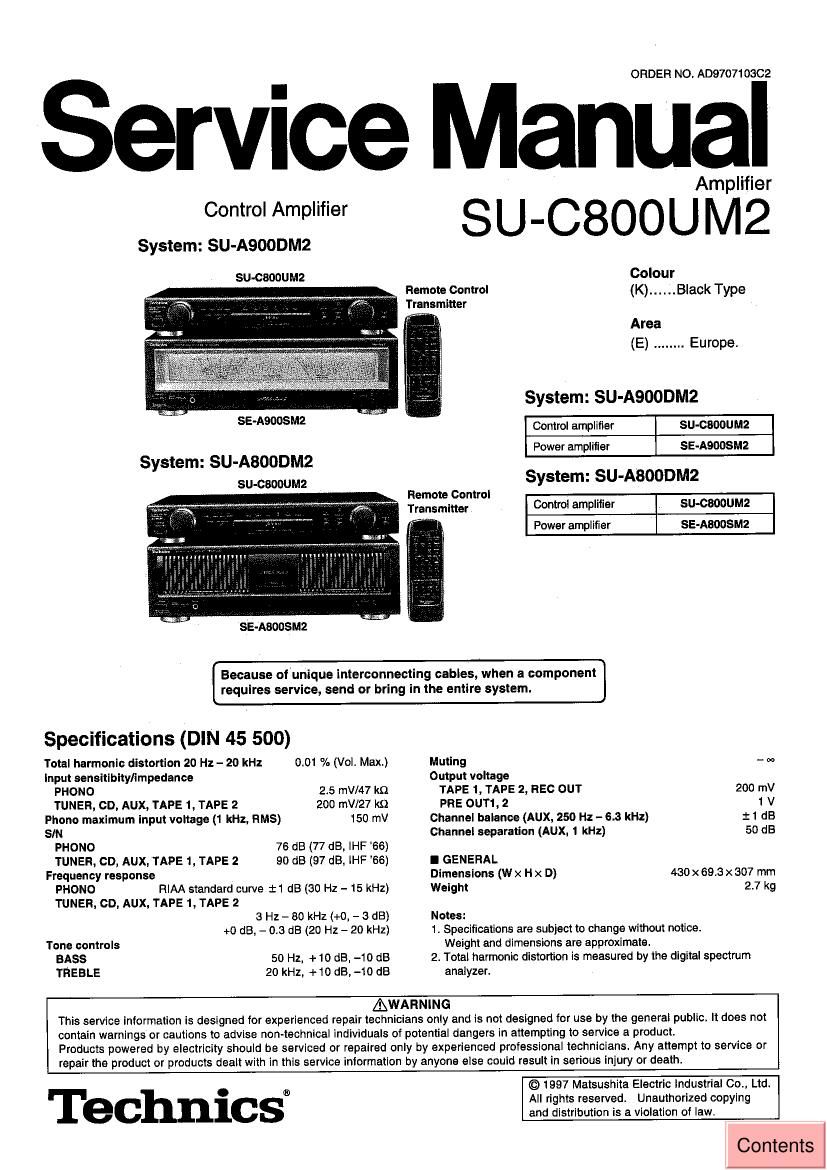
Technics SUC 800 UM 2 Service Manual
This is the 18 pages manual for Technics SUC 800 UM 2 Service Manual.
Read or download the pdf for free. If you want to contribute, please upload pdfs to audioservicemanuals.wetransfer.com.
Extracted text from Technics SUC 800 UM 2 Service Manual (Ocr-read)
Page 1
ORDER NO. AD970710302
Service Manual
Control Amplifier
System: SU-A900DM2
SU-CBOOUM2
Amplifier
Colour
Remote Control (K) ...... Black Type
Transmitter
" Area
(E) ........ Europe.
System: SU-A9OODM2
SE-ASOOSMZ Control amplifier SU-CBOOUMZ
Power amplifier SE-AQDOSMZ
System: SU-ABOODMZ
su-ceooumz System: SU-A800DM2
Remote Control _ _
Tmnsmmfl Control amplifier SU-CEDOUMZ
' Power amplifier se-Asoosmz
SE-ABOOSMZ
Because of unique interconnecting cables, when a component
requires service, send or bring in the entire system.
Specifications (DIN 45 500)
Total harmonic distortion 20 Hz - 20 kHz 0.01 % (Vol. Max.) Muting - w
Input sensitibitylimpedance Output voltage
PHONO 2.5 mV/47 kfl TAPE 1, TAPE 2, REC OUT 200 mV
TUNER, GD, AUX, TAPE 1, TAPE 2 200 mV/27 k9 PRE 0UT1, 2 1 V
Phono maximum input voltage (1 kHz, HMS) 150 mV Channel balance (AUX, 250 Hz - 6.3 kHz) :1 dB
SIN Channel separation (AUX, 1 kHz) 50 dB
PHONO 76 dB (77 dB, IHF '66)
TUNER, CD, AUX, TAPE 1. TAPE 2 90 dB (97 dB. lHF 66) I GENERAL
Frequency response Dimensions M x H x D) 430 >< 69.3 x 307 mm
PHONO FllAA standard curve :1 dB (30 Hz - 15 kHz) Weight 2.7 kg
TUNER, CD, AUX, TAPE 1, TAPE 2
3 Hz - 80 kHz (+0, - 3 dB) Notes:
+0 dB, - 0.3 dB (20 Hz - 20 kHz)
Tone controls
BASS 50 Hz, +10 dB. -10 dB
TREBLE 20 kHz, +10 dB,-1O dB
1. Specifications are subject to change without notice.
Weight and dimensions are approximate.
2. Total harmonic distortion is measured by the digital spectrum
analyzer.
AWARNING
This service information is designed for experienced repair technicians only and is not designed for use by the general public. It does not
contain warnings or cautions to advise non-technical individuals of potential dangers in attempting to service a product.
Products powered by electricity should be serviced or repaired only by experienced professional technicians. Any attempt to service or
repair the product or products dealt with in this service intormation by anyone else could result in serious injury or death.
Technics®
© 1997 Matsushita Electric industrial 00., Ltd.
All rights reserved. Unauthorized copying
and distribution is a violation of law.
Contents
Page 2
SU-CBOOUMZ
I Contents
Page
Front Panel Controls ........................................................................... Wiring Connection Diagram ............................
Operation Check and Type Illustration of IC's, Transistors and Diodes
Main Component Replacement Procedures Block Diagram ........................... .t
To Supply Power Source . Replacement Parts List (Electrical) .. .. 15 , 16
Terminal Function of IC's . Replacement Parts List (Cabinet) ..
Schematic Diagram ...... Replacement Parts List (Resistors and Capacrtors) ..
Printed Circuit Board Diagram Cabinet Parts Location .........................................
N
NOTE:
Refer to the service manual for Model No. SE-ASOOSMZ (ORDER No. AD970709962) or SE-ABOOSM2 (ORDER No.
ADQ707098C2) for information on Accessories", Connections" and Packaging.
I Front Panel Controls
(D Power STANDBY (I) ION" switch
? 9066 (POWER, STANDBY (DION)
Press to switch the unit lrom on to standby mode or vice versa.
in standby mode. the unit is still consuming a small amount oi
power.
C)
i>
The control amplifier switches between ON and the standby
mode only It the power amplifier POWER switch is in the " -.
0@ (D ON" position,
® input selector/Indicators (SELECTOR)
© Muting indicator (MUTING)
G) Tone control button (TONE)
Cs) Tone controls (BASS, TREBLE)
© Volume control (VOLUME)
(3 STANDBY" indicator (STANDBY)
When the power amplllier POWER switch Is in the " LON"
posilion, this indicator lights up in standby mode and goes out
when the unit is turned on.
Remote control signal sensor (SENSOR)
® Tape-monitor button/indicators (TAPE MONITOR)
® ADVANCED VIRTUAL BATTERY OPERATION"
indicator
® Balance control (BALANCE)