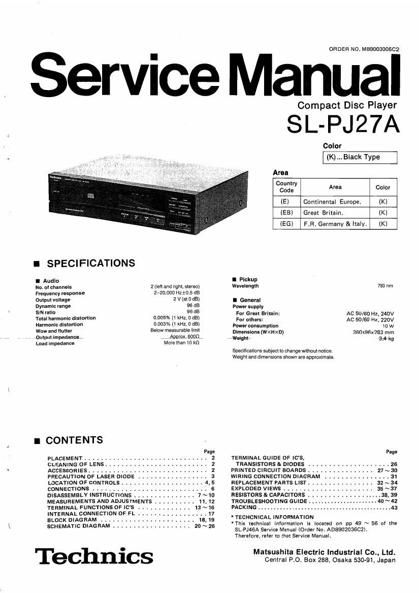
Technics SLPJ 27 A Service Manual
This is the 35 pages manual for Technics SLPJ 27 A Service Manual.
Read or download the pdf for free. If you want to contribute, please upload pdfs to audioservicemanuals.wetransfer.com.
Extracted text from Technics SLPJ 27 A Service Manual (Ocr-read)
Page 1
t.
0R DE R NO. M89003005C2
ice Manual
Compact Disc Player
SL-PJ27A
Color
(K) Black Type
Area
08:22" Area Color
(E) Continental Europe. (K)
(EB) Great Britain. (K)
IEG) F.R. Germany 8t Italy. (K)
I SPECIFICATIONS
I Audio I Pickup
No. of channels 2 (left and right. stereo) Wavelength 730 "m
Frequency response 2-20,000 Hzrots dB
Output voltage 2 V (al 0 dB) I General
Dynamic range 95 15 Pawer supply
SIN ratio 96 dB For Great Britain: Ac 50/60 Hz, 240v
Total harmonic distortion 000596 (1 kHz, 0 dB) For othsrs: AC 50/60 HZ, 220V
Harmonic distonlon 0.003% (1 kHz, 0 dB) Powarcongumpfian to w
Wow and "utter Below measurab'e m" Dimensions (WXHXD) 360x96x283 mm
Outpuumpedanca , ~ JPDKOXQQDQr Walghtrr {Hr kg
Load impedance More than 10 K!)
Specifications subject to change without notice.
Weight and dimensions shown are approximate
I CONTE NTS
Page Page
PLACEMENT ............ TERMINAL GUIDE OF IC'S,
CLEANING OF LENS . TRANSISTORS & DIODES .................... 26
ACCESSORIES. A .
PRECAUTION OF LASER DIODE .............
LOCATION OF CONTROLS . . . . . .
CONNECTIONS ......... . , . .
DISASSEMBLV INSTRUCTIONS ......
MEASUREMENTS AND ADJUSTMENTS .
TERMINAL FUNCTIONS OF IC'S .....
INTERNAL CONNECTION OF FL . ................ 17
BLOCK DIAGRAM ....................... 18.19
SCHEMATIC DIAGRAM . ...... . . . . . . ...... 20~26
Technics
PRINTED CIRCUIT BOARDS
WIRING CONNECTION DIAGRAM .
REPLACEMENT PARTS LIST .......
EXPLODED VIEWS ...... . .
RESISTORS & CAPACITORS
TROUBLESHOOTING GUIDE
PACKING ..................
* TECHCNICAL INFORMATION
*This technical information is located on pp 49 ~ 56 of the
SL»PJ46A Service Manual (Order No. AD8902036C2I.
Therefore, refer to that Service Manualt
27~30
. . .31
32~34
Matsushila Electric Industrial Co., Ltd.
Central PO. Box 288, Osaka 530-91, Japan
Page 2
S -PJ27A
I PLACEM ENT
I Before placement
Two transport security devices are secured to prevent the optical
pickup from damage during transport.
Be sure to release them before use,
LOCKED RELEASED
insert them here after removing.
Turn clockwise by 90° to secure
them.
Soft cloth or similar material (to
prevent scratch es)
Note:
When transporting the unit, be sure to remove the compact disc
from inside the unit. And replace the transport security devices
again following the reverse order not to damage the optical pickup.
I CLEANING OF LENS
If the lens is stained causing sound skip or operation failure,
open the top cover by pressing the open button, and clean
the lens.
0 To remove dust or dirt
Blow the lens with the blower provided in the cleaning kit
to remove dust or dirt.
Dust or dirt Fingerprint
0 To remove fingerprint
if the blower is not enough, moisten the cotton rod
with the lens cleaner solution and wipe the lens with it
from center of the lens to outside.
I ACCESSORIES
0 AC power supply cord ........ 1
[SFDACOSEOS (E, 5(5)]
SJA188 (EB)
O L-tvpe cable ................ i
(SJP2257T)
I Notes of placement
I This unit is a precision instrument. Be sure to place it on a
flat surface.
I Avoid places such as the following:
ONear any equipment or device that generates strong magnetism.
OOn any heat-generating equipment or device. or in any piece
where the temperature is high (35°C or higher).
OExtremeiy cold places (5°C or below).
INear a tuner or TV (It may cause noise in the broadcast, or
disturbance of the TV picture.)
I when carrying orstoring the unit, handle it with care so it is
not subjected to any strong bumps.
Always remove the disc before storing the unit for any period of
time.
I To avoid problems due to vibration.
000 not place a book or similar object under this unit.
oDo not route the connection cables (of this or other units) across
the operation panel, across the top, or under the unit.
Cautions:
I Do not directly apply the cleaner solution to the lens.
Do not apply too much solution to the cotton rod or
otherwise the solution will flow into the player.
0 Wipe the lens carefuilv. Do not give too much stress to
the lens or otherwise it may SCratch the lens or cause
optical pickup trouble.
,E..,.,,.,. ml tit hrsolution'rs hould~ be 100"muci'r"flppl icdr wi pc~thevvri *7
lens with a dry cotton rod.
Lens cleaning kit (Part No. : SZZP1038C)
0 Stereo connection cable ......... 1
(SJP2249-3)
Page 5
, r®vfiepoatindicatorifn
SL-PJ27A§
32EE7§§fi>fifififififl>
[ Indicators section
@ Programmed-play indicator ( )
® Track number display (TRACK)
® Index/program number display (NO./INDEX)
® Auto cue indicator (A. CUE)
Q Time display (MIN/SEC)
® Pause indicator(l I)
@ Play indicator(l>)
@ Over" mark (>)
This indicator tights it the total number of tracks on the disc is
17 or more.
® Track number indicator (24:6)
w Tape side indicator (NB)
6 Compact disc edit indicator (EDIT)
If this unit is connected with Technics Hi-Fi compo-
nent system whose remote control transmitter has
Efl button for compact disc operation, the pause
function may not be activated by pressing the E]
button during compact disc play.
Page 15
0 IC401 (MN187164PJW3): System control 8: FL drive
Pin IIO i Pin |/O
F i
No. Mark Division unctlon No. Mark Division Fummon
1 SEGG 28 P10 l Track loss input
1 I O F L segment signal
7 SEGO 29 RST 1 Reset command
FL drive power supply Sub-code frame clock
8 VPP (connected to -31 AV) 3° P05 ' (7.35 kHz)
Power supply 31 P04 | Subcode 0 data
9 VDD ' (Connected m 49v)
Disc holder open/close det.
1o OSC2 | Clock terminal 32 P03 I signal input
11 08C1 I Clock input Subcode 0 data block clock
33 SBTO l 75 Hz)
12 V53 - GND terminal
Drop out detector/Tracking
Xl I Digital input of sign 34 $30 0 servo ON signal output
3 (nez - Hell
35 P00 l Status command for CRC em
14 X0 - Net used, open
36 SYNC - Not used, open
15 P27 0 Synchro rec control terminal
37 CM - GND terminal
16 P26 0 Loading motor control signal
38 P47 0 Divide-by 4 output
17 P25 0 Mut'mg control signal
f 39 P46 0 Deemphasis command
On/off control (start input);
18 P24 l/O ready signal output (starting 40 p45 I pLL 0,, hold input
up procedure successful)
41 P44 .
19 P23 Output control bits for off-, I g I Key rem" Signal and key scan
I Z 0 Catch, play« status and DAC 45 F41 5'9"3'~
22 P20 output current
45 DGTO
23 mm l Remote control signal 2 I 0 FL digit signal and key scan signal
61 DGT15
Digital input of sign F7
24 IRQO I (R22 - R91) 62 P61 0 Synchro rec control signal
25 P13 0 Mode control data 6} SE68 0 FL nt . l
64 SEG7 segme slgna
26 P12 0 Data clock for MDATA
Load command for mode
27 P 0 control data
_15_
Page 19
- SCHEMATIC DIAGRAM
(Parts list on pages 32 ~ 34, 40, 41.)
(This schematic diagram may be modified at any time
with development of new technology.)
flsaRvo CIRCUIT
.. i
-_--l®
i
2 I 3 l 4 l 5 l
OPTICAL PiCKUF
FOCUS RADTAL i
id
w
E 2}
N4
\_9i£_
c
ossoz
G)
BC338
Notes: . 7 J 5352:. i H
- S1 : Power switch in "on" position. 7 mm (a J \ 31mm 'M
-s613 : Play (> PLAY) switch. av at. - \ /\
- :31: :gkip (h (i4 ) s)witch. iceso4 W225: 5.27:4; 2.. 06502 g [Tiff
° : earc (4 switch. I 5 2 ooui "
-se16 : Program (PROGRAM) switch. ngvvwl# § 53
'5617 1 Auto cue (A CUE) switch. new .w hm i
'8619 : Step (I STOP) switch. GACT: a}:
'5620 : Skip ( N ) switch.
~5621 : Search ( p» i switch. 5%
08623 : Tape side select (SIDE A/B) switch. cgfll'éot
'8624 : Random (RANDOM) switch. am i
'8626 : Disc holder open/close (A OPEN/CLOSE) switch. him {my P7-
-sez7 : Pause (ll PAUSE) switch. W
-sszs 2 Repeat (REPEAT) switch. LEE 527:3; W:
0 8629 : Clear (CLEAR) switch. ANN E,
-SG30 :Edit(EDIT) switch. * 2w wv ow 5 w
- 8631 : Time mode select (TIME MODE) switch. 9., MW was.
'81001 : Tray (OPEN/CLOSE) switch. WW "oww i fig
Sms czv/nw E:
- The voltage value and waveforms are the reference voltage of 3:i 0650,
this unit measured by DC electronic voltmeter (high impedance) EETSEQSOCR
and oscilloscope on the basis of chassis. g 7 -« , 77
Accordingly, there may arise some error in voltage values and
. . . Focus otisei on,
waveforms depending upon the internal Impedance of the tester A V
or the measuring unit. MW W \ K m i
The parenthesized are the values of voltage generated during 51. NW N \ a (WWWW 1%.! W 47/. .
playing (Test disc 1kHz, L+R, OdB), others are voltage values \ #3 V 06:7 REF/Sinsmomwniv ospsczi/uiv
in stop mode. 3) [drawn 5 9 i 1;:
- Important safety notice: E \ ' W gééa m 5° M ,-
Components identified by A mark have special characteristics m Dsfiuafeém :/2' 352502 ($353. 33 52 ge g; '31; 2% £5
impu. m... ful few. wm wins. u... f w W V n m, Hm J" i A :- . S The, .23.,
use only manufacturer's specified parts. W 5572 V 2 *L 5 o. '6 in 7h: '3 a 3 ea 0 m 2 22 1 5. m gutse w
.-< >-/--< >N: Positive voltage lines and negative PQ-siai-ANHD 2 W 2% 0 J E i L 9 i a (L 150 mo iii/{£3 4 Li
voltage lines. %__m (7% 5w ,
cameo : Audio signal lines. E? 020549 {1-
Caulionl ¥
IC and LSI are sensitive to static electricity. 5V
Secondary trouble can be prevented by taking care during repair.
0 Cover the parts boxes made of plastics with aluminum foil. "-6504
- Ground the soldering iron. Ifisififiim
' Put a conductive mat on the work table.
° Do not touch the pins of IC or LSI with fingers directly.
-
a
ELK
_ 21 i
_20._