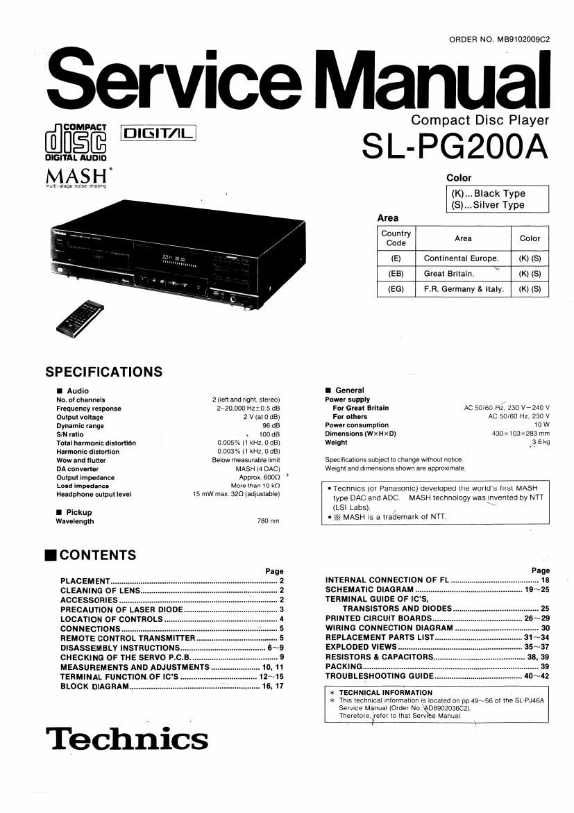
Technics SLPG 200 A Service Manual
This is the 34 pages manual for Technics SLPG 200 A Service Manual.
Read or download the pdf for free. If you want to contribute, please upload pdfs to audioservicemanuals.wetransfer.com.
Extracted text from Technics SLPG 200 A Service Manual (Ocr-read)
Page 1
ORDER NO. MBQ10200902
Service Manual
Compact Disc Player
SL-PG 200A
mulllrslage nurse shapmg
SPECIFICATIONS
I Audio
No. 0' channels
Frequency response
2 (left and right, stereo)
2720,000 Hzi0,5 (15
Output voltage 2 v (at 0 dB)
Dynamic range 96 dB
S/N ratio w 100 dB
0 005% (1 kHz. 0 dB)
0.003% (1 kHz, 0 dBl
Below measurable IlmlI
MASH (4 DAC)
Approx. 500:)
More than to k0
15 mw max 320 (adjustable)
Total harmonic dislortidn
Harmonic distortion
Wow and llutter
DA converter
Output impedance
Load impedance
Headphone output level
I Pickup
Wavelength 780 hm
.CONTENTS
'5
a:
Q
m
PLACEMENT ..........
CLEANING OF LENS
ACCESSORIES ..........................
PRECAUTION 0F LASER DIODE
LOCATION OF CONTROLS
CONNECTIONS .....
REMOTE CONTROL TRANSMITTER
DISASSEMBLV INSTRUCTIONS.
CHECKING OF THE SERVO P.C.B
MEASUREMENTS AND ADJUSTMENTS
TERMINAL FUNCTION OF ICS .
BLOCK DIAGRAM.
commentators:
Technics
Color
(K)...B|ack Type
(S)...Si|ver Type
Area
Country
Code Area Color
(E) Continental Europe. (K) (8)
(EB) Great Britain. (K) (S)
(EG) FR Germany & Italy. (K) (S)
I General.
Power supply ,r
For Great Britain AC 50/60 Hz. 230 V-240 V
For others AC 50/60 Hz, 230 V
Power consumption 10 W
Dimensions (WXHxD) 430x103><283 mm
Weight 3 6 kg
Specifications sublect to change wuthcut notice
Weight and dimensions shown are approximate
. TecthS (or Panasonic) developed the world's first MASH
type DAC and ADC MASH technology was invented by NTT
(LSI Labs). , \
- >'< MASH l5 a trademark ol NTT
INTERNAL CONNECTION OF FL.
SCHEMATIC DIAGRAM
TERMINAL GUIDE OF ICS,
TRANSISTORS AND DIODES
PRINTED CIRCUIT BOARDS ......
WIRING CONNECTION DIAGRAM
REPLACEMENT PARTS LIST
EXPLODED VIEWS ............
RESISTORS 8r CAPACITOR
PACKING ............................
TROUBLESHOOTING GUID
* TECHNICAL INFORMATION
* This technical Inlormatlon 5 located on pp 49~56 oi the SLrPJASA
Service Manual (Order No DBSOZOSBCZ)
Thereiore,2rrelerlotha1 Servl 9 Manual
1
Page 2
w
I PLACEMENT
LBefore placement
Two transport security devices are secured to prevent the optical
pickup lrom damage during transport,
Be sure to release them belore use
LOCKED RELEASED
,, err/Insert them here alter removmg.
Turn clockmse by 90" to secure
them.
V//Soft cloth or similar material (to
prevent scratches)
When transporting the unit. be sure to remove the compact disc
lrom inSIde the unit. And replace the transport security devices
again lollowmg the reverse order not to damage the optical pickup
I CLEANING OF LENS
If the lens is stained causing sound skip or operation failure,
open the top cover by pressing the open button, and clean
the lens.
I To remove dust or dirt
Blow the lens With the blower prowded in the cleaning kit
to remove dust or dirt.
Dust or am Fingerprint
0 To remove fingerprint
If the blower is not enough, moisten the cotton rod
With the lens cleaner solution and Wipe the lens With it
from center of the lens to OUISlde.
I ACCESSORIES
[ Notes of placement 1
I This unit is a precision instrument. Be sure to place it on a
flat surface.
I Avoid places such as the lollowing:
INear any equment or deVice that generates strong magnetism
IOn any heat-generating equipment or device, or in any place
where the temperature is high (350 or higher).
tExtremely cold places (5°C or below).
ONear a tuner or TV (It may cause n0ise in the broadcast, or
disturbance of the TV picture.)
I When carrying or storing the unit, handle it with care so it is
not subjected to any strong bumps.
Always remove the disc before storing the unit for any period of
time.
I To avoid problems due to vibration.
0Do not place a book or similar object under this unit.
000 not route the connection cables (of this or other units) across
the operation panel, across the top, or under the unit.
Cautions:
0 Do not directly apply the cleaner solution to the lens.
Do not apply too much solution to the cotton rod or
otherWise the solution Will flow into the player
Wipe the lens carefully. Do not give too much stress to
the lens or otherWise it may scratch the lens or cause
optical pickup trouble,
if the solution should be too much applied, Wipe the
lens With a dry cotton rod.
Lens cleaning kit (Part No. :SZZP1038C)
\
. /
Blower
OStereo connection
cable (SJP224973).
OAC powersupply cord
f8JAl87 (E, E6) 1
\SJAlQS (EB) /
0 Remote control transmitter
(BIack: EUR64798iJ y y 1
__(Silver: EUR64799)
IBatteries (UM-4NE/28). ., . 2
N
Page 4
I LOCATION OF CONTROLS
Yhe function. indicated by the black numbers (with white background. ® etc.) can also be Ictlvated using the remote control transmitter.
4567
I Control section
0 Power "STANDBY (ii/ON switch
(POWER 1 STANDBY t') - 0N)
This switch switches ON and OFF the secondary circuit power
only The unit is in the ' standby" condlltnn when this swltch is
set to the STANDBY L') position Regardless DI the switch
setting the primary Ctrcul| is always live" as long as the
power cord is connected to an electrical outlet
9 Disc holder
0 Remote control signal sensor
(REMOTE SENson)
@ Search buttons (« SEARCH »)
These buttons can be used to move rapidiy iorward or
backward on the disc during play, The search speed ls slow
when the button is pressed at Itrst and becomes taster ii the
button is pressed and held continuously.
© Buttons for program Iunotlon
uProgram button (PROGRAM)
Pressing this button initiates the program play mode
iron can then enter specilic hacks using the numeric
buttons
Oclear button (CLEAR)
Each pressing this button makes one track cleared erm the
programmed sequencer
nRecall button (RECALL)
This button can be used to display the contents Di the
programmed track sequence Ior oonlirrnetion.
© Edit tape length button (TAPE LENGTH)
When compact discs are to be recorded to tape. this button
can be used to calculate the number or tracks that can be
recorded on each side or the tape depending on the length or
the cassette tape used. so that as little tape as possible is
wasted
® Tape-side select button (SIDE A/B)
When recording compact discs to tape, this button can be
used to check the number 01 tracks and amount DI lave tell
over lot side A or B.
0 Disc link button (DISC LINK)
This button can be used lor edit recording liom several discs,
9 Time race button (TIME FADE)
Pressing this button in the pause or stop mode causes the
lads-out Iunclion to work at the specified time
Pressing this button In the edit mode causes the lode-out
lunctlon to work at the and at the have when lhe track added
exceeds the remaining time or the tape
Time mode select button (TIME MODE)
(9 Random play button (RANDOM)
This button can be used to play the tracks on a dlsc in a
random sequence
® Repeat button (REPEAT)
® Headphones volume control (LEVEL)
Avoid listening to music at high volume levels tor
extended periods ot time.
Q Headphones lack (PHONES)
@ Auto cue button (AUTO CUE)
Pressing this button enables the unit to step at the beginning
at every track and switch to the play standby mode,
Peak level search button (PEAK SEARCH)
Pressing this button enables the unit to search tor the peak
Signal" locations in tracks on a disc so as lo adjust the suitable
recording level on the cassette deck.
® Play button (> PLAY)
Pause button (ll PAUSE)
Stop button (I STOP)
This button can be used to stop disc play, as well as to cancel
the various play modes,
@ Sklp buttons ( l« SKIP, »I SKIP)
These buttons can be used to spaclly the number of the
destred track and the desired recording time cl the tape,
® Dlso holder open/close button
(A OPEN/CLOSE)
(D (D
tfiACK anEx um sec
i i
PGM - LEVEL , _ .
05 Hal -ElB. HE [E *
APEAK L. No( ALUE T.FADE I I
soimiiiisszssnnww
Urinurnbered buttons on the remote
control transmitter Iunmion identically
to their corresponding parts on the
unit.
I Indicators section j
Q Disc link indicator (LINK)
® Program play indicator (FGM)
0 Track number display (TRACK)
@ Index/program number display (INDEX, Not)
© Auto one indicator (A. CUE)
2D Level indicator (LEVEL)
This indicator lights when the output level is attenuated by the
remole control,
@ Time display (MIN, SEC)
® Operation Indicators
The lollowlng indicators tight during their respective opera-
tions
-m Peak level search
A-B repeal play (remote control operation)
El' Repeat play
-,Random play
ml: Time tade (Iadcroull
w Flay indicator (
0 Pause indicator (I )
@ "Over mark (>)
This indicator lights it the total number at tracks on the dlsc is
7 at more
® Track number indicator (i-fa)
w Tape side indicator (ask-ea)
@ Compact disc edit indicator (EDIT)
@ Peak level search Indicator (PEAK)
LRemote control transmitter
@ Level buttons (V LEVEL A)
These buttons can be used to adjust output level (train 0 dB In
42 dB),
GD A-B repeat button (A-B REPEAT)
This bullori can be used to play the portion 0' a disc between
two points (A arid B) chosen by you,
Q) Numeric buttons (>10. 0, 1~1o)
® Remote control signal transmission window
VOOZOd'WS