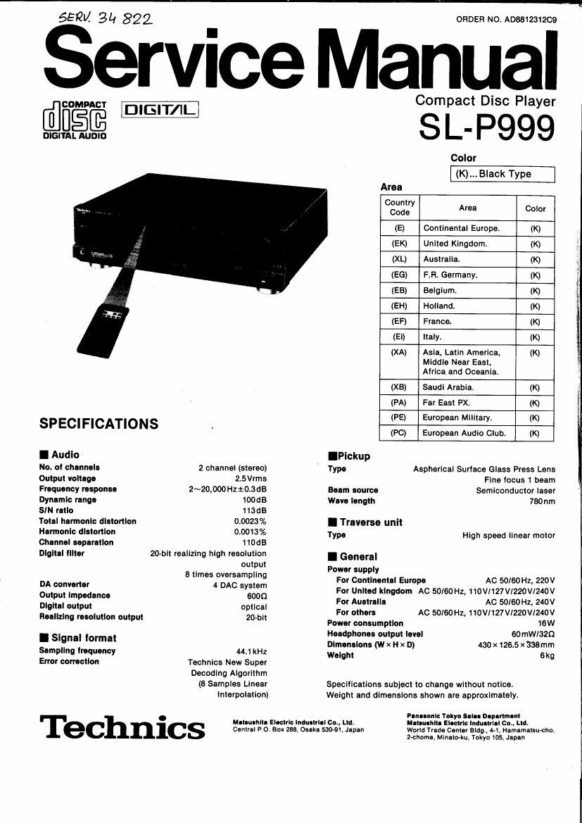
Technics SLP 999 Service Manual
This is the 47 pages manual for Technics SLP 999 Service Manual.
Read or download the pdf for free. If you want to contribute, please upload pdfs to audioservicemanuals.wetransfer.com.
Extracted text from Technics SLP 999 Service Manual (Ocr-read)
Page 1
55W 3L1 822
ORDER NO A08812312C9
ervice Manual
@fi°§@_
DIGITAL AUDlO
SPECIFICATIONS
I Audio
No. of channels 2 channel (stereo)
Output voltage 2.5Vrms
Frequency response 2~20,000 Hzt0.3dB
Dynamic range 100dB
SIN ratio 113118
Total harmonic distortion 0.0023%
Hannonlc distortion 0.0013%
Channel separation 11MB
Digital tllter 20-bit realizing high resolution
output
8 times oversampling
DA converter 4 DAC system
Output impedance 6000
Digital output optical
Realizing resolution output 20-bit
I Signal format
Sampling frequency 44.1 kHz
Error correction Technics New Super
Decoding Algorithm
(8 Samples Linear
interpolation)
. mun-nu. Electric lnduetrlal oo., Ltd.
ec nlcs Central Po. Box 253. Osaka 530-91.Jepan
Compact Disc Player
SL- P999
Color
(K)... Black Type
Area
Country
Code Area Color
(E) Continental Europe. (K)
(EK) United Kingdom. (K)
(XL) Australia. (K)
(EG) F.R. Germany. (K)
(EB) Belgium. (K)
(EH) Holland. (K)
(EF) France (K)
(Ei) Italy. (K)
(XA) Asia, Latin America, (K)
Middle Near East,
Africa and Oceania.
(XB) Saudi Arabia, (K)
(PA) Far East PX. (K)
(PE) European Military. (K)
(PC) European Audio Club. (K)
IPickup
Type Aspherical Surface Glass Press Lens
Fine focus 1 beam
Beam source Semiconductor laser
Wave length 780nm
I Traverse unit
Type High speed linear motor
I General
Power supply
For Continental Europe AC 50/60 Hz, 220V
For United kingdom AC 50/60 Hz, 110V1127Vl220V1240V
For Australia AC 50/60 Hz, 240V
For others AC 50/60H2, 110V/127V1220VI2AOV
Power consumption 16W
Headphones output level 60mW/32Q
Dimensions (w x H x D) 430 x 126.5 x338mm
Weight 6kg
Specifications subject to change without notice.
Weight and dimensions shown are approximately.
Panasonic Tokyo Sale. Department
Maleuehltl Electric Industrial Co., Ltd.
World Trade Center Bldg 4-1, Hamamalsutho,
2~chome. MlnelMu. Tokyo 105, Japan
Page 2
.L-PQQQ
I CONTENTS
1
u
a
O
PLACEMENT...
ACCESSORIES
PRECAUTION OF LASER DIODE.
CONNECTIONS ..........................
REMOTE CONTROL TRANSMITTE
LOCATION OF CONTROLS
BASIC OPERATION ..
HANDLING PRECAUT 0N8 FOR OPTICAL C U .
INSTRUCTIONS FOR TRAVERSE OIL
(Part No. SZZOL31) .................
DISASSEMBLY INSTRUCTIONS..
MEASUREMENTS AND ADJUSTMENT
TERMINAL FUNCTION OF ICS
INTERNAL CONNECTION OF FL ..... 26
BLOCK DIAGRAM .
Nyl :
mamaawnn
I PLACEMENT
Before placement
The optical pickup is secured to prevent damage during transport.
Be sure to release it before use.
.9
(with inclinationl) Lock shaft Pull to unlock,
' (in the locked
7. condition)
6
0 Note:
When carrying this unit, be
I» sure to remove the compact
disc from inside the unit, and
press the lock shaft to secure
the optical pickup. (Make
sure to place the unit with the
rear panel facing downward.)
Soft cloth or similar material (to prevent scratches)
SCHEMATIC DIAGRAM ................................................. 32~l1
TERMINAL GUIDE OF lCs,
TRANSISTORS AND DIODES...
WIRING CONNECTION DIAGRAM
PRINTED CIRCUIT BOARDS.
TROUBLESHOOTING GUIDE
PACKING.. 53
RESISTORS AND CAPACITORS 54, 55
REPLACEMENT PARTS LIST 56~58
EXPLODED VIEW ................
REPLACEMENT PARTS LIST
EXPLODED VIEW ................ 61, 62
REPLACEMENT PARTS LIST . 63
EXPLODED VIEW................ . 64
Notes of placement
I Place on a flat, level surface so that the front-rear
Incllnatlon does not exceed 5°.
I Avoid places such as the following:
cNear any equipment or device that generates strong magnetism.
IOn any heat-generating equipment or device. or in any place
where the temperature is high (40°C or higher).
IExtremer cold places (5°C or below),
tNear a tuner or TV (It may cause noise in the broadcast, or
disturbance ot the TV picture.)
I Do not place heavy objects, other than system compo-
nents, on top of the unlt.
I When carrying or storing the unit. handle It with care so It Is
not subjected to any strong bumps.
Always remove the disc before storing the unit for any period of
time,
I To avoid problems due to vibration.
0Do not place a book or similar object under this unit,
~00 not route the connection cables (at this or other units) across
the operation panel, across the top. or under the unit.
OAC power supply OStereo connection OOptical cable . .. ., . 1 ORemote control UBatteries ............ 2
cord ................ 1 cable .............. 1 transmitter .......... 1
SJA187 (E, E6, EB, EH, EF, Ei) (SJP2249A4) (SJPD16) (EUR64729) (UM-4NEIZS)
SJAt 73 (XL)
SJA193 (EK)
SJA168-1 (XA, PA, PE, PC)
SJA183 (x3)
Page 4
I LOCATION OF CONTROLS
SL-P999
The functions Indicated by the black numbers (with white background, @ etc.) can be also activated using the remote control transmitter.
4
I Control section I
0 Power switch (power)
6 Disc holder
9 Remote control signal sensor
(remote sensor)
@ Numeric buttons (+10, 0, 1~20)
(5) Clear button (clear)
This button can be used to clear tracks from the programmed
sequence one at a time.
© Programmed-play button (program)
Pressing this button initiates the programmed play mode. You
can then enter specific tracks using the numeric buttons
® Recall button (recall)
This button can be used to display the contents of the
programmed track sequence tor confirmation.
9 Window search button (window)
Press this button to perform searches when the unit is in the
pause modes Search for any point on the disc using the
search dial. Release the dial at the desired point and that
point on the disc is repeated again and again.
9 Edit tape length button (- tape length)
When compact discs are to be recorded to nape. this button
can be used to calculate the number of tracks that can be
recorded on each side of the tape. depending on the length at
the cassette tape used, so that as little tape as possible is
wasted.
® Tape-side select button (side A/B)
When recording compact discs to tape, this button can be
used to check the number at tracks and amount oi tape leit
over for side A or B.
@ Disc link button (disc link)
This button can be used for edit recording from several discs.
Q Search dial (search)
This dial can be used to locate specific places on the disc
during play at high speed. either forward or reverse.
@ Peak level search button (peak search)
This button can be used to locate the maximum signal level
(peak level) for the signals on the disc.
567
Time mode select button (time mode)
® Display mode select button (display mode)
@ Digital output button (digital output) .
This button can be used to switch to on and oil for digital
output.
@ Auto cue/auto space button
(_I- auto space)
Pressing this button causes the unit to switch to the play
standby mode.
When editing. this button can be used to insert the silent gaps
between the tracks.
Random play button (random)
This button can be used to play the tracks on a disc in a
random sequence.
Repeat button (repeat)
® A-B repeat button (A-B repeat)
This button can be used to play the portion oi a disc between
two points (A and B) chosen by you.
® Play button and indicator (b play)
® Pause button and indicator (ll pause)
® Stop button (I stop)
This button can be used to stop disc play. as well as to cancel
the various play modes.
® Index skip buttons (-index/index-)
These buttons can be used to skip by index number (smaller
divisions within specific tracks).
(23 Skip buttons ( H4 skip/skip >>i )
These buttons can be used to skip by track in the lorward or
reverse direction.
® Disc holder open/close button (A open/close)
@ Timer start switch ((1) timer)
This switch allows you to use a separately purchased audio
timer to switch the unit on automatically at a preset time.
w Headphones volume control (phones level)
Avoid listening to music at high volume levels for
extended periods of time.
@ Headphones jack (phones)
SL-P999
69 Q? @ Eli Cllj
[it - - l-Ii-I r, I-I -l-I [-7 I 1 window --- digital
$2321" [7 ['7 :l Jud-D -I .I C restrtpzn _- output
- -track index min
was -
b, .
We? .2: as
| indicators section I
® Random play indicator (random)
Q Programmed-play indicator (program)
@ Disc indicator (_)
® Track number display (track)
® index/program number display (index/No.)
@ Time display (min/sec)
The indicators display the iollowing types of time information.
elapsed: time elapsed since the beginning of the current
selection
remain": time remaining until the end of the current
selection '
"total: total elapsed time since the beginning of the
disc or total time remaining until the end oi the
disc. depending on whether the elapsed" or
remain" indicator is illuminated.
@ Operation indicators
The indicators below illuminate during their respective opera-
tions.
_: window search
_ auto cue
E: auto space
El: peak level search
-: A-B peak level search and A-B repeat play
-: repeat play
® Digital output Indicator ( )
@ Emphasis indicator (emphasis)
This indicator illuminates when discs recorded with pre-
emphasis in the high-frequency range are played.
G2
unnumbered buttons on the remote
control transmitter function identically
to their corresponding pads on the
unit.
@ Over" mark (h)
This indicator lights if the total number of tracks on the disc is
21 or more.
® Play position/output level indicator
This indicator toggles between its 2 modes each time the
display mode select button is pressed.
0 Track number indicator (j-E)
Q Disc link indicator (lfll)
® Compact disc edit indicator (_)
m Tape side indicator (- AIB)
I Remote control transmitter
® Remote control signal transmission window
® Search buttons (44 search >>)
These buttons can be used to move rapidly toward or
backward on the disc during play. The search speed is slow
when the button is pressed at first and becomes faster if the
button is pressed and held continuously.
0 Display switch (display on/otf)
This switch allows you to turn oft the display during play if you
wish.
The display returns lot about 5 seconds whenever an
operation button is pressed and then goes out again.