Technics SLCA 10 Service Manual
This is the 42 pages manual for Technics SLCA 10 Service Manual.
Read or download the pdf for free. If you want to contribute, please upload pdfs to audioservicemanuals.wetransfer.com.
Extracted text from Technics SLCA 10 Service Manual (Ocr-read)
Page 1
ORDER NO. AD951226908
Service Manual
Compact Disc Changer
SL-CAI 0
CD Changer
compAcT
U§@ its... m... m...
merrAL Aunlo
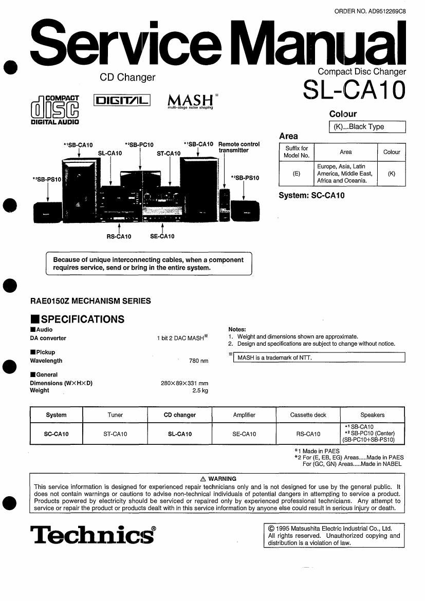
SB-CAN Remote control
transmitter
SB-CA10 SB-P010
SL-OA10 ST-CAIO
zSB-PS1 0
SB-PS1 0 2
SE-CAI 0
RS-CAtO
Because of unique interconnecting cables, when a component
requires service, send or bring in the entire system.
RAE015OZ MECHANISM SERIES
ISPECIFICATIONS
IAudlo Notes:
DA converter 1 bit 2 DAC MASH 1-
Colour
(K)...B|ack Type
Area
5:3; It); Area Colour
Europe, Asia, Latin
(E) America, Middle East, (K)
Africa and Oceania.
System: SC-CA10
Weight and dimensions shown are approximate.
2. Design and specifications are subject to change without notice.
IPlckup -
Wavelength 780 nm MASH IS atrademark oi NTI.
IGeneraI
Dimensions (WXHX D) 280x89><831 mm
Weight 2.5 kg
System Tuner CD changer Amplifier Cassette deck Speakers
*1 SB-CAt D
sc-oA1 o ST-CA1 o SL-CA10 SE-CA1 o RS-CAt o *2 $843010 (Center)
(SB-Pcm+se-Ps1 0)
*1 Made in PAES
*2 For (ELEB, EG) Areas ..... Made in PAES
For (GC, GN) Areas ..... Made in NABEL
A WARNING
This service information is designed for experienced repair technicians only and is not designed for use by the general public. It
does not contain warnings or cautions to advise non~technical individuals of potential dangers in attempting to service a product.
Products powered by electricity should be serviced or repaired only by experienced professional technicians. Any attempt to
service or repair the product or products dealt with in this service information by anyone else could result in serious injury or death.
Technics°
© 1995 Matsushita Electric Industrial 00., Ltd.
All rights reserved. Unauthorized copying and
distribution is a violation of law.
Page 2
SL-cmii
I CONTE NTS
Page
PRECAUTION OF LASER DIODE .. 2 TROUBLE SHOOTING (SERVO CIRCUIT) ..
LOCATION OF CONTROL .......... 3 BLOCK DIAGRAM .....
LISTENING TO COMPACT DISCS. 3 SCHEMATIC DIAGRAM .
HANDLING PRECAUTIONS FOR TRAVERSE DECK.. 4 PRINTED CIRCUIT BOARD DIAGRAM
REPLACEMENT OF THE FOOT ................................ .. 4 WIRING CONNECTION DIAGRAM
OPERATION CHECK AND MAIN COMPONENT TERMINAL GUIDE .....................
REPLACEMENT PROCEDURES ..................................... 5~16 RESISTORS AND CAPACITORS .
ERROR CODE DISPLAY AND SERVO REPLACEMENT PARTS LIST
ADJUSTMENT FUNCTION ............. 17, 18 CABINET PARTS LOCATION
MEASUREMENTS AND ADJUSTMENTS . . 19 LOADING MECHANISM PARTS.
NOTE:
Refer to the service manual for Model No. SE-CAto (ORDER No. A0951227208) for information on "ACCESSORIES",
INSTALLATION , CONNECTIONS and PACKAGING.
IPRECAUTION OF LASER DIODE
CAUTION: This product utilizes a laser diode with the unit turned "on", invisible laser radiation is emitted from the pickup
lens.
Wave length: 780 nm .
Maximum output radiation power from pickup: 100 pWNDE
Laser radiation from the pickup lens is safety level, but be sure the followings:
1. Do not disassemble the optical pickup unit, since radiation from exposed laser diode is dangerous.
2. Do not adjust the variable resistor on the pickup un'rt. It was already adjusted.
3. Do not look at the focus lens using optical instruments.
4. Recommend not to look at pickup lens for a long time.
ACHTUNG: Dieses Produkt enthalt eine Laserdiode. lm eingeschalteten Zustand wird unsichtbare Lesersirahlung von der
Lasereinheit abgestrahlt. .
Wellenlange: 780 nm
Maximale Strahlungsleistung der Lasereinheit: 100 uWNDE
Die Strahlung an der Lasereinhelt ist ungefahrllch, wenn folgende Punkie beachtet werden:
1. Die Lasereinheit nicht zerlegen, da die Strahlung an der freigelegten Laserdiode gefahrlich ist.
2. Den werkseilig justierten Einstellregler der Lasereinhit nicht verstellen.
3. Nicht mit optischen lnstrumenten in die Fokussierlines blicken.
4. Nicht iiber langere Zeit in die Fokussierlines blioken.
at?
DANGER INVISIBLE min tritium WHEN DFEII.
ADVAIISEL 5
VARD!
VARNlNG
ADVAFISEL WE
VORSICHT W Wmmm.»m Mm
I99
murmur.
imam
CLASS 1 '
LASER PRODUCT
LUOKAN 1 LASERLAITE
KLASS 1 LASER APPARAT
CAUTION! .
THIS PRODUCT UTILIZES A LASER.
USE OF CONTROLS 0R ADJUSTMENTS OR PERFORMANCE OF PROCEDURES OTHER THAN
THOSE SPECIFIED HEREIN MAY RESULT IN HAZARDOUS RADIATION EXPOSURE.
_2_
Page 19
SL-CA10
IMEASUREMENTS AND ADJUSTMENTS
Cautions:
0 It is very dangerous to look at or touch the laser beam. (Laser radiation is invisible.)
With the unit turned on" , laser radiation is emitted from the pickup lens.
0 Avoid exposure to the laser beam. especially when performing adjustments.
This unit SL-CA10 is designed to operate on power supplied from the Amplifier SE-CA1 0 through the Tuner ST-CAtO.
When connecting the unit to other system components, do not connect to the Amplifier SE-CA10 directly. Be sure to connect this
unit through the Tuner ST-CA10.
When operating the unit SL-CA1O alone for testing and servicing, without having power supplied from the Amplifier SE-CA1O and
the Tuner ST-CA1 0, use the following method.
Power Supply to This Unit alone
1. Short-circuit the section between jumper (J13) and jumper (J14) [TEST MODE ].
2. Apply 11V AC power to the section between of the coil (L1) and the jumper (J3) ml as well as the section between
of the coil (L2) and the jumper (J3) -. (Shown in Fig. 1)
- Operating the Unit Alone
When this unit is operated,alone without system connection to other units, the switches on the front panel remain inoperative. To
operate the switch%, follow the procedure below.
1. Short-circuit the points between the jumper (J1 1 ), the jumper (J1 2) and the [-].
2. Short-circuit the points between the jumper (J15), the jumper (J1 6) and the [-1.
To Check Signals
Connect the oscilloscope or the speaker with built-in amplifier to the section between LINE OUT (Lch) of the resistor R447 and the
GND point of the jumper (J3) as well as the section between LINE OUT (R ch) of the resistor R448 and the GND point of the jumper
(J3) and check if the signals are outputting from this unit. (Shown in Fig. 1)
POWER SUPPLY JIG
n
33 13, 3311?, 1'23
/ Unsoldered side 0 GND 0 0 0+
\ o e o o o o-
Soldered side
Note: '
The above symbol indicates ajumper soldered Corl (L1)
on one side. When this jumper is levered up AC 11V
usinga a screwdriver, its unsoldered side is Jumper (J3)
raised so that it can be seized with an alligator AC 11V
clip. COII(L2)
ACt1V-
R447 j ACth-wr
[LINE OUT(L ch)] Coil L1 AC 1
(Signal check) ( ) - Coil (L2) Jumper (J3)
m E
6'
@ g
.114; 3 J13 KEV 2 -'
-0
Li 3'}? 4:1 Sho rt JW" R443
[6 MAIN P.C.B. Short Jm+ [LINE OUT(R oh)]
. (Signal check)
J12 -0
J11 4:] 3