Technics SC CH700 Owners Manual

This is the 80 pages manual for Technics SC CH700 Owners Manual.
Read or download the pdf for free. If you want to contribute, please upload pdfs to audioservicemanuals.wetransfer.com.

Page: 1 / 80
Technics SC CH700 Owners Manual

Extracted text from Technics SC CH700 Owners Manual (Ocr-read)


Page 1

@ Printed in Japan

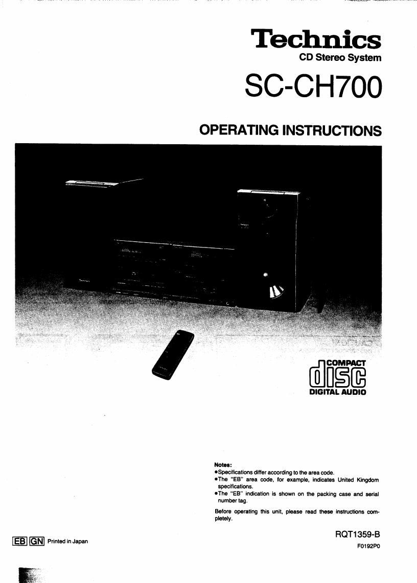
Technics

CD Stereo System

SC-CH7OO

OPERATING INSTRUCTIONS

' 7"M_

will. I i,

DIGITAL AUDIO

Notes:

oSpecilications differ according to the area code.

OThe EB" area code, for example, indicates United Kingdom
specifications.

OThe "EB indication is shown on the packing case and serial
numberteg

Before operating this unit, please read these instructions com-
pletely.

RQT1359-B

F01 92P0

Page 2

Z

We want to thank you for selecting this product and to
welcome you to the growing family of satisfied
Technics product owners around the world.

We feel certain you will get maximum enjoyment

from this new addition to your home.
Please read these operating instructions carefully,

and be sure to keep them handy for convenient
reference.

These operating instructions are applicable to the Ioiicwing systems.

System CD player/Tuner Amplifier Sound processor Cassette deck Speakers
SC-CH7oo SL-CH700 SU-CH700 SH-CH700 Rs-cmoo SB-CH700
Suggestions for Safety .................... Making a Recording ....................... 41
For United Kingdom ............ . . . ......... 3 Edit-Recording from Compact Discs ......... 45
Placement Notes ......................... 4 Tape-to-Tepe Recording . .................. 52
Supplied Accessories .................... . 4 Using the Timer . . . . . . ..... . . . . . . ......... 53
Concerning the Remote Control . . . . . ........ 5 Creating Your Own Sound ................. 58
How to Install the System .................. 6 Enjoying the Microphone Mixing ..... . ...... 67
Connections ............................ 7 Using an External Unit . . . . . . . ............. 69
Front Panel Controls and Functions ......... 14 Concerning the Display .......... . . . . . . . . . .70
Basic Operating Procedure ................. 24 Concerning Cassette Tapes . . . . ............ 71
Setting the Time .......................... 27 Concerning Compact Discs ..... . . . . . . . . . . .72
Listening to Compact Discs . . . . . . ..... . . . . .28 Maintenance .......... . ............... . . .73
Listening to Tapes ..... . . . . . . ........... . .34 Troubleshooting Guide . . . . . . ....... . . . . . . .74
Listening to Radio Broadcasts .............. 38 Technical Specifications ........ . ......... . .76

CAUTION!

THIS PRODUCT UTILIZES A LASER.

USE OF CONTROLS OR ADJUSTMENTS 0R PER-
FORMANCE OF PROCEDURES OTHER THAN THOSE
SPECIFIED HEREIN MAY RESULT IN HAZARDOUS
RADIATION EXPOSURE.

DO NOT OPEN COVERS AND DO NOT REPAIR
YOURSELF. REFER SERVICING TO QUALIFIED
PERSONNEL.

IIAIIIIEII-lmisim
laser relief-n Mm

AVOID DII'IICT EX-
POSURE TD BEAM.

CLASS I
LASER PRODUCT

(Buck ol product)

(mam)

THIS TUNER/RECEIVER IS CAPABLE OF RECEIVING THE NEW AM STEREO BROADCASTS FROM THE AM BAND
RADIO STATIONS. HOWEVER LIKE MANY TUNERS AND RECEIVERS CURRENTLY AVAILABLE ON THE MARKET
IT WILL REPRODUCE THIS AM STEREO SIGNAL ONLY IN AM MONO, WHICH, IN EFFECT, IS OF NO LESSER
QUALITY THAN YOUR EXISTING AM MONO TUNER/RECEIVER.

Page 16

5 Front Panel Controls and Functions

(continued)

Luueose

Amplifier section

® Loudness button (S. LOUDNESS)
This button is used to boost the dynamic low frequency ranges
in a low volume level,

® Input select buttons

(DAT, CD, VDP, VCR, TAPE, TUNER, PHONO)
These buttons are used to select the sound source to be
heard.

® Volume level control (VOLUME)
This control is used to adjust the volume level.
Note that -- dB" is the lowest volume setting and "0 dB" is the
highest level setting.
® Power STANDBY @ION" swltch
(POWER STANDBY (DION)
This switch switches ON and OFF the secondary circuit power
only. The unit is In the standby" condition when this switch is
set to the STANDBY 0) position. Regardless oi the switch
setting, the primary circuit ls always "live" as long as the
power cord is connected to an electrical outlet.

@ Headphones )eck (PHONES)

@ Clock eet button (CLOCK SET)
This button is used to set the present time.

® Timer select buttons (v SELECT A)
These buttons are used when setting the time, making the
timer setting, selecting the type of timer operation, etc.

@ Timer set button (TIMER SET)
This button is used to enable the timer set mode and the
current selection. selected by the timer select buttons.

@ Timer cancel button (CANCEL)
This button is used to cancel the timer setting.

@ Timer standby button (STANDBY)
This button is used to cancel the timer setting temporarily.

® Timer setting continuation button (RECALL)
This button is used to confirm the timer settings.

@ Microphone volume control (MIC VOL.)
This control is used to adjust the microphone volume level.

@ Microphone lack (MIC)

69 Balance adiuetment buttons (BALANCE)
These buttons are used to adjust the volume balance.

Page 18

t Front Panel Controls and Functions

(continued)

\ W mm

Sound processor section

® Equalizer frequency Indicator (E0 FREO)
® Ettect indicator (EFFECT)

@ Sound ettect level control (JOG)
This control is used for adjusting the level of surround sound
effect. equalization level and specific irequency shiit.

@ Equalizer ONIFLAT button -, ON/FLAT)
This button is used to switch the equalizer on or flat.

@ Equalizer trequency select buttons
(V BAND A)

These buttons are used to select one of the desired equaliza-
tion frequency bands (LOW, HIGHt, HIGHZ).

® Equalizer level-control buttons (- LEVEL +)
These buttons are used to adjust oi equalization level.

® Slope (0) select button [SLOPE (0)]

® Fixed mode select button (FIXED MODE)
This button is used to select the fixed mode at equalization
curve or ambienoe enhancement.

® User mode select button (USER MODE)
This button is used to select the user mode oi equalization
curve or ambiance enhancement.

® Memory button (MEMO)
This button is used to store an original equalization curve or
ambiance enhancement.

® SFP OFF/ON button
-, OFF/ON)
This button is used to activate ambiance enhancement.

® Demonstration button (DEMO)
This button is used to change sound effects sequentially.

® Voice mute button (KARAOKE)
This button is used to change "karaoke" (using microphone
with en ewompanirnent).

® Display mode select button
(DISPLAY, -SPECT RUM -MODE)
This button is used to select one otthree spectrum displays. It
you press and hold this button. the equalization curve is
displayed together with the spectrum display.

® Jog mode button (JOG MODE)
This button is used to select the mode at adjusting with sound
eitect level control.

Page 65

ON/FLAT SLOPEiQ)

l:|

To adjust the level of the specific
frequency

With this system the frequency of interests can be freely selected
with equalizer frequency select buttons, matching It with the music
source. and you can enjoy sound as you like it

Furthermore, this unit has a built-in constant 0 circuit so it has
minimum effect on adjacent frequencies because the wrve slope
(Q) is large and very fine adjustment is possible.

Before continuing, select the desired equalization curve end/or
surround sound mode. (See page 58 and 62.)

(While playing the desired source.)

1 Press one of the equalizer frequency select
buttons to select the desired frequency.

Each time one of the equalizer frequency select buttons Is
pressed. LOW. HiGHl , HIGHZ will be alternately displayed.

LOW: 31 .5-220 Hz range
HIGHt: 315 Hz-16 kHz range
HIGHZ

2 Press one of the equalizer level control but-
tons to adjust the frequency level.

+
:1 2 When inueasethelevel
[:1 : When decrease the level
I To change the curve slope
The curve slope selection changes from "narrow" mode to "wide"
mode and vice versa each time the slope (0) select button Is
pressed.

Press the slope (a) select button.
SLOPEtO)

in the wide" mode the adjacent cursors will be boosted more than
white in the "narrow" mode.

I To shift the curve slope
The curve slope can be shifted within the range of 31 .5-220 Hz
or 315 Hz-16 kHz.

Shift the curve slope using the sound effect level
control.

G : When shift the curve slope from the low frequency
sound to the high frequency sound.

© : When shift the curve slope from the high frequency
sound to the low frequency sound.

In adiust the reverberation sound after the
above settings have been done

Press the log mode button to Illuminate the ef-
fect indicator, and then proceed to the step 3 on
page 64. (When the SFP indicator illuminates,)

em
-Z<:>i-
I To bypass the graphic equalizer
(When the SFP indicator illuminates)
Press the equalizer ON/FLAT button to select

FLAT.
The "USER" display will illuminate.

0mm

CI

Note:

The curve slope cannot be shifted within the range from 31 .5-
220 Hz to 315 Hz-ts kHz. That can not also be shifted from
315 Hz-16 kHz to 31 .5-220 Hz.