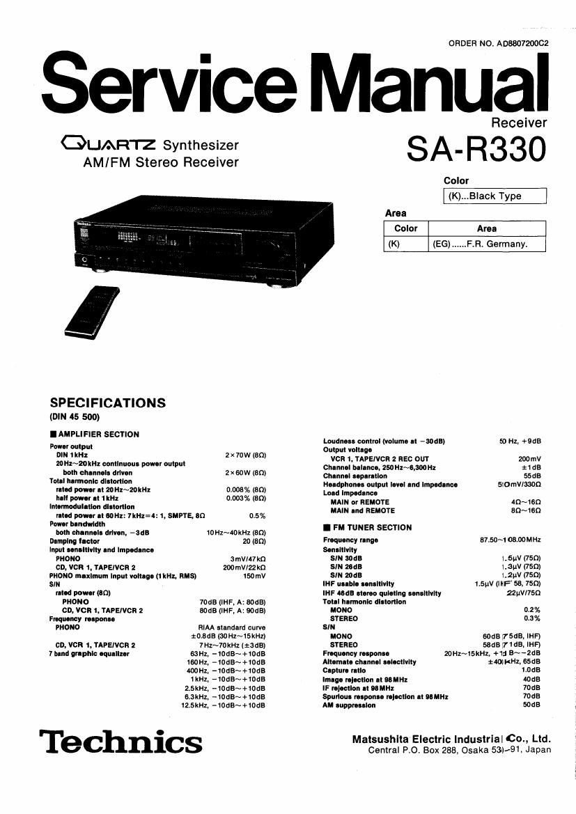
Technics SAR 330 Service Manual
This is the 28 pages manual for Technics SAR 330 Service Manual.
Read or download the pdf for free. If you want to contribute, please upload pdfs to audioservicemanuals.wetransfer.com.
Extracted text from Technics SAR 330 Service Manual (Ocr-read)
Page 2
SA-R33O
sum uplrullon 1 HI: 40118 I GENERAL
10kHz 3DdB
Clrrhr Ink 19k": -60dB (-ssas. IHF) P' W: :::;:y"'"'°" AC 50mm HZ g)":
It": -70dB(-75dB, IHF) '
cnannol b-Innco (250H1~5,m Hz) 1:15:15 'm'm'm' (W x H X 9) (16.157332231219013:
mm" M 12" wugm 6.7kg (14am)
BIndedflI
IF nmpll'kr 180 kHz
FM demodulator 1000kHz Notes: . .
Am... tumlnlls 750 (unbalanced) 1 Specifications are sublact to change wIthout notlce.
Walnht and dlmenslons are approxlmate.
2. Total harmonIc dIstonlon Is measured by the dlgltal spectrum
I AM TUNER SECTION analyzer (HP. 3045 system).
anuoncy fungi 522N1611 kHz (9 kHz-steps)
530~1620I
SelmleIy It 999ka 55:13
Imagl rolocIlon al MkHz 4DdB
IF rolocuon n 999 kHz 55dB
I CONTENTS
Page
ACCESSORIES ................... BLOCK DIAGRAM .......................................... . 22~24
LOCATION OF CONTROL 3~5 DESCRIPTION OF FLUORESCENT DISPLAY.
CONNECTIONS .............. 6, 1 TERMINAL GUIDE OF ICS.
PROTECTION CIRCUITRY. 7 TRANSISTORS AND DIODES 26
BEFORE REPAIR AND AD . 7 PRINTED CIRCUIT BOARDS ........
DISASSEMBLY INSTRUCTIONS ........ WIRING CONNECTION DIAGRAM . . 31
MEASUREMENTS AND ADJUSTMENTS . 11. 12 SCHEMATIC DIAGRAM ..... 32~38
FUNCTION OF TERMINAL .. CABINET PARTS LOCATION 39, 40
RESISTORS & CAPACITOR REPLACEMENT PARTS LIST . 41
REPLACEMENT PARTS LIST.. REMOTE-CONTROL PARTS LOCATION . 42
SCHEMATIC DIAGRAM OF REPLACEMENT PARTS LIST .............. . 42
REMOTE-CONTROL TRANSMITTER
I ACCESSORIES
- FM indoor antenna (1) . AM loop antenna (1) 0 AM antenna holders (2) . Screws (2)
(SSA270M) (SPB1162T)
as &
(SMA233«1 M) (SMA231 M) (XTN3+10AFZ)
. Connection cable tor remote-control (1) ' Flat cable tor remote-control (1) - Remote-control o Batteries (2)
(SJP2257T) (SWKST11M-1) transmitter (1) (UM-4NEI23)
CD
a:
(Eunwss)
Page 5
. Connections to speakers
This unit
1*) (-) r-) (+)
\L->
SA-R330
I Load impedance:
MAIN or REMOTE: 4~16 0
MAIN and REMOTE: 8~16 n
IREMOTE" terminals
For connection to a second
pair at speakers.
Speaker connection cords (option)
Connection of speaker wires
, . . (D Notes: +
0) TYN'S the °°e ° the $993k w'ws =3 10 mm 1. To prevent damage to circuitry, never 0
® Llft Up the lever. and Insert the cote 4. H (ta/32) shortcircuit positive (+) and negative (-)
until it can no longer be seen. =,_ Twist speaker terminals.
© Press down the lever. and 9" the 2. Be sure to only connect positive l+)
cord gently to be sure that it Is secure. (D 41: cords to positive (4.) terminals, and
._1 negative (-) cords to negative (-) terminals.
\ 3.
Connections of speaker wires should be made before
connecting the AC power supply cords.
I PROTECTION CIRCUITRY
The protection circuitry may have operated if either of
the following conditions is noticed:
- No sound Is heard when the power is turned on.
- Sound stops during a performance.
The function of this circuitry is to prevent circuitry
damage if, for example, the positive and negative
speaker connection wires are shorted", or If speaker
systems with an impedance less than the indicated
rated Impedance of the amplifier are used.
I BEFORE REPAIR AND ADJUSTMENT
1. Turn off the power, Discharge both power supply
capacitors (C701, C702 8200uF) through a 100 SW
resistor to ground. Do not short between C701 and
C702. It may damage the capacitors.
If this occurs, follow the procedure outlines below:
1. Turn off the power.
2. Determine the cause of the problem and correct it.
3. Turn on the power once again after one minute.
Note:
When the protection circuitry functions, the unit will
not operate unless the power Is first turned off and
then on again.
2. After completion of repair, slowly apply the primary
voltage by using a variac to avoid over cu rrent.
Current consumption at 50Hz/60Hz In no signal
mode should by shown with respect to supply
voltage 220V.
Power supply voltage
AC 220V
Consumed current 50/60 Hz 170~370 mA
Page 10
. FUNCTION OF TERMINAL
0 |CQO1 (LCB554H3682): microcomputer
SA-R330 SA-R33O
I
i
l
PIN NO. MARK IIO DESCRIPTION OF TERMINAL
1 (Egg) 0 Segment signal output
2 PM
3 S
5 PAS
v - I Key return signal input
6 P80
3 S
8 PB2
9 (ST [5488 BY) l Power supply terminal
PCO -
10 (OFF) I Power ONIOFF lnput
11 (STFER1E0) I Stereo signal input
P02
12 (SD) I SD elgnal Input
13 530;; HO Deck control terminal
14 (REERY) 0 Relay control output
15 (73(1) 0 Deck control terminal
16 NC -- Not connected
17 NC - Not connected
18 (Pb/['58 O Auto/mono changeover terminal
19 (Rigs/I) O Muting control output
PE2
20 (AT) 0 Attenuator control output
21 (APESI) 0 AF signal muting control output
22 TP - Ground terminal
23 V35 - Ground terminal
24 0801 | Oscillator terminal
25 0362 0 Oscillator terminal
26 RES I Reset signal Input
27 PFOID1 0 Serial data output terminal
28 PF1ICK 0 Clock signal terminal for serial data
29 PF2/CE 0 Chip enable termlnal
30 PFSIW I Remote control input
31 D1 - Ground terminal
-13.,
PIN N0. MARK IIO DESCRIPTION OF TERMINAL
32 (PC?) - Ground terminal
33 {5% 0 Control slgnal terminal for IC401 (T09163N)
34
S NC - Not connected
37
38 Fla 0 Loudness control out ut
(LOUDNESS) P
39 PJO (R)
- - 0 Volume motor drive output
40 PJ1 (F)
41
- NC - Not connected
42
43 Vp I Power supply terminal (negative voltage)
44 S1
3 S 0 Segment signal output
55 S12
57 D1
5 s 0 Digit signal output and key scan signal output
64 08
56 V99 I Power supply terminal (positive voltage)
14-