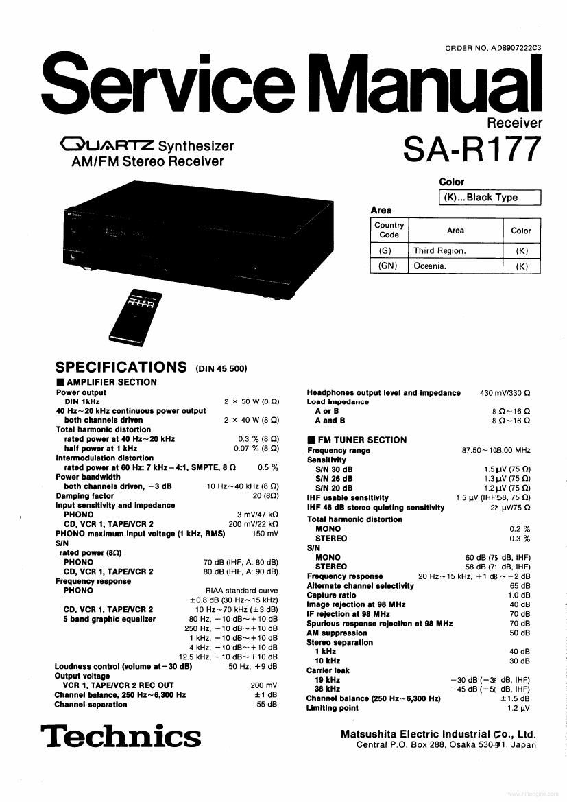
Technics SAR 177 Service Manual
This is the 30 pages manual for Technics SAR 177 Service Manual.
Read or download the pdf for free. If you want to contribute, please upload pdfs to audioservicemanuals.wetransfer.com.
Extracted text from Technics SAR 177 Service Manual (Ocr-read)
Page 2
SAVRI77
Bandwidth
IF lmpllllor 180 kHz
FM demodulalor 1000 kHz
Antenna tennlnaln 75 Q (unbalanced)
I AM TUNER SECTION
Frequency range 522 kHz~1611 kHz (Q-kHz steps)
530 kHz~1620 kHz (10-kHz steps)
Sonslllvlly (SIN 20 dB) 20 IN, 330 uVIm
Selecllvlly at 999 kHz 55 dB
Image mlmlon an 999 kHz 40 08
IF rolecflon (II 999 kHz) 55 dB
Pm
CONNECTIONS T0 EQUIPMENT ................ . . . . .2
BEFORE USE ................ .
REMOTE CONTROL OPERATION
ACCESSORIES .....................
FRONT PANEL CONTROLS AND FUNCTIONS . .
DISASSEMBLY INSTRUCTIONS ............
PROTECTION CIRCUITRY ....... .
BEFORE REPAIR ................
MEASUREMENTS AND ADJUSTMENTS
TERMINAL FUCTION OF IC ....... .
I CONNECTIONS T0 EQUIPMENT
-Antenna connection terminals
"GND" terminal
I GENERAL
Power consumpllon 250 w
Power eupply
For Oceania AC 50 H2160 Hz, 240 V
For Third Region AC 50 HZ/GO HZ, 110 V1127 Vl220 VI240 V
Dimensions (w x H x D) 430 x 114 x 300 mm
(16-15l16" X 4-1/2 x 1143/16")
Wolght 6.3 kg (13.9 lb.)
Nola:
Total harmonic dislorlion is measured by lhe digital spectrum
analyzer.
BLOCK DIAGRAM ................ .
INTERNAL CONNECTION OF FL ......
SCHEMATIC DIAGRAM ..... . . . .
PRINTED CIRCUIT BOARDS ........
WIRING CONNECTION DIAGRAM .
EXPLODED VIEW ............
REPLACEMENT PARTS LIST.
EXPLODED VIEW.
RESISTORS Br CAPACITORmS ............... . .
Speaker connection terminals-
Voluge selector
(For (6) area only.)
TAPE/VCR? VCRI
D O O 0 \AC m
0 Q 0 REMOTE CONTROL
E mom: cu REC mv n c Puv om PE
our BAEK our BACK ? I7_'-_'I
L_.._I L___I
-AC IN socke1(AClNI
"PHON0"_J
terminals --Remote-control tape terminal
(about 150pF) -"VCR 1.. mini; (Connect a tape deck.)
Remote-control terminal
L"rAPENcn 2" Terminal: (Connect a tape deck and/or ormpact
I- disc player.)
"CD" terminals
Phono input capacitance is about 1:0pF.
Page 6
SA R177
I DISASSEMBLY INSTRUCTIONS
ATTENTION SERVICER"
Some chassis components may have sharp edges.
Be careful when disassembling and servicing.
2. Remove the speaker switch & headphones
jack P.C.B. in the direction of the arrow.
1" Removal of the cabinet *sz Removal of the front panel
Procedure . Remove the 5 screws ( 0" 6)} PdeWB 1. Remove the 1 screw ( 0 ).
1 1 '* 2 2. Remove the 1 connector (J705).
3. Remove the 3 flat cables (J502,
9 J604, J605).
Cabinet
0 H-I-Rj
Gk. .
0 i iillllll
92% l W
\.
J502
» ., «Jeos l
0 iJSOIi JVOSV-Dé 1:3
We 1 J
4. Remove the volume knob and nut.
5. Remove the 4 screws (0 ~ 6 ).
Ref. No. Removal of the DOWEI' switch P.C.B., 6. Pull out the front panel in the direction of
3 speaker switch & headphones jack P.C.B. the arrow.
and power source P.C.B.
Procedure
1 *2 "3 1. Remove the 3 screws (0 ~ 0 ),
Front panel
Volume knob
0
Ref. No. Removal of the F L/graphic equalizer
4 P.C.B.
Procedure 1. Remove the 6 screws (0 ~ 6).
Speaker switch 81 1'2 *3 4 2. Remove the FL/graphic
headphones jack P.C.B. equalizer in the
direction of the
. V \
/ FL/graphic
, I ;. equalizer P.C.B. W0
\\
39
/
Power source P.C.B.