Technics SAGX 303 Service Manual

This is the 49 pages manual for Technics SAGX 303 Service Manual.
Read or download the pdf for free. If you want to contribute, please upload pdfs to audioservicemanuals.wetransfer.com.

Page: 1 / 49
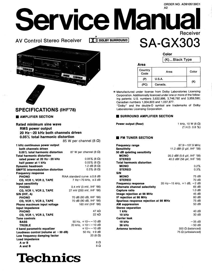
Technics SAGX 303 Service Manual

Extracted text from Technics SAGX 303 Service Manual (Ocr-read)


Page 2

SA-GX303

I AM TUNER SECTION

Frequency range 530~1720 kHz

Sensitivity 20 W, 330 uV/m
Selectivity 55 dB
Image rejection at 1000 kHz 40 (13
IF rejection at 1000 kHz 60 dB

I VIDEO SECTION

Output voltage at 1 V input (unbalanced)
Maximum input voltage

Input/output impedance 75 Q (unbalanced)

I CONTENTS
Page

SAFETY PRECAUTION ................................................................ 2
REAR PANEL TERMINALS AND FUNCTIONS.
ACCESSORIES .......................................
FRONT PANEL CONTROLS AND FUNCTIONS
DISASSEMBLY INSTRUCTIONS
INTERNAL CONNECTION OF F .

MEASUREMENTS AND ADJUSTMENTS
TERMINAL FUNCTION OF ICS
BLOCK DIAGRAM ..

I G EN ERAL

Power consumption 275 W, 370 VA

Power supply AC 120V, 60Hz

Dlmensions (W x H x D) 430 x134 x 305 mm
(16-15/16" X 5-9/32" X 12")

Weight 8.5 kg (13.7 lb.)

Notes:

1. Specifications are subject to change without notice. Weight
and dimensions are approximate.

2. Total harmonic distortion is measured by the digital spectrum
analyzer.

SCHEMATIC DIAGRAM
TERMINAL GUIDE OF I ,
DIODES ...................................

WIRING CONNECTION DIAGRAM 46
PRINTED CIRCUIT BOARDS . 41~53
EXPLODED VIEWS .............. 54, 55

REPLACEMENT PARTS LIST
RESISTORS & CAPACITORS.
PACKING

I SAFETY PRECAUTION (This safety precaution is applied only In U. S. A.)
.Before servicing, unplug the power cord to prevent an electric shock.

, When replacing parts, use only manufacturer' 5 recommended components for safety.

. Check the condition of the power cord, Replace if wear or damage is evident.

, After servicing, be sure to restore the lead dress, insulation barriers, insulation papers, shields, etc.

. Before returning the serviced equipment to the customer, be sure to make the following insulation resistance test to
prevent the customer from being exposed to a shock hazard.

O INSULATION RESISTANCE TEST

1, Unplug the power cord and short the two prongs of the plug with a jumper wire.

2. Turn on the power switch.

3, Measure the resistance value with ohmmeter between the jumpered AC plug and each exposed metal cabinet part, such as
screwheads antenna, control shafts. handle brackets, etc. Equipment with antenna terminals should read between 3M9
and 5,2MQ to all exposed parts. (Fig. A) Equipment without antenna terminals should read approximately infinity to
all exposed parts. (Fig. B)

Note: Some exposed parts may be isolated from the chassis by design, These will read infinity.

0"wa

Antenna
terminal \

Ex posed Exposed 5
metal metal
part part
Ohmmeter Ohmmeter
(Fig.A) (Fig.8)

Hesistance=3MQ-5,2MQ ResistancezApprox oo
4. If the measurement is outside the specified limits, there is a possibility of a shock hazard. The equipment should be

repaired and rechecked before it is returned to the customer.

Page 8

SA-GX303

r-Tuner controls
Fly. 1

Function selector controls
Fig. 3

(GD-B-

woéééé

-@

6666(5)

k

r« SKlP »r

(-Cassette deck controls

bmv ISTOP "muse @

CJCJCJOO

CD

momw
ooN'rINuE

SELECTOR _
VCR! vcH2;

Fig. 2

DD
(5 DECK

41 » I

dFLAY b

SURROWD wan LEVELA

[DEED

I:

IPAUSE

CJDD

.STOF

«new »FF

0 Rec

ll PAUSE
VCR

DC]

> PlAV I STOP

MUTING v

VOLUME

A

Remote control section

Tuner controls (Fig.1)
@ Power switch (POWER)

This power switch is used for controlling the power (ON/OFF) oi
this system as well as any Panasonic remote controlled TV
and/or VCR.

When switching the power of each unit 0N and OFF, be sure to
first press the appropriate function selector button on the
remote control transmitter.

Cassette deck controls (Fig.2)

® Preset-tuning buttons (1 -0)
These buttons are used to tune to broadcast stations that have
been preset to the unit's memory.
When these buttons are used, be sure to first press the
TUNER" button of the function selector buttons on the remote
control transmitter.

Record button (. REC)

Press this button to change to the recording stand-by mode.

® Deck Deck 2 selector (DECK 1I2)
This button is used to select the deck to be operated by
remote control when a double cassett deck is connected with
this unit,

® Fast-torwardlcuelrewindlreview buttons

(44, >>)

Press this button to advance or rewind the tape while the unit
is in the stop mode.

Press this button to cue or review the contents at high speed,
while the unit is in the play mode.

® Playback buttons (4 PLAY >)
To begin playback or recording, press one of these buttons cor-
responding to the side of the tape to be played (or recorded).
>1 For the A-side of the tape
4: For the B"-side of the tape

®Pause button (II PAUSE)
Press this button to temporarily stop playback or recording.
Press the playback button to resume the play or recording.

it Stop button (I Stop)

To stop tape movement.

Function selector controls (Fig.3)

® Function selector buttons
(TUNERl TV, VCR, CD)

These buttons are used to change the functions of this remote
control.

._10_