Technics SACH 1501 Service Manual

This is the 48 pages manual for Technics SACH 1501 Service Manual.
Read or download the pdf for free. If you want to contribute, please upload pdfs to audioservicemanuals.wetransfer.com.

Page: 1 / 48
Technics SACH 1501 Service Manual

Extracted text from Technics SACH 1501 Service Manual (Ocr-read)


Page 2

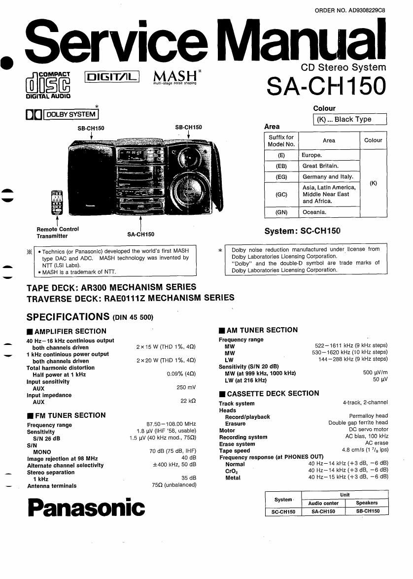
SA-CH150

SIN (CrOz type tape)
Dolby NR olf
Dolby NR on
Wow and llutter
Fast forward and rewlnd tlme
Approx. 110 seconds with C-SO cassette tape

52 dB (A-WTD)
51 dB (CCIR)
0.1% (WRMS)

I CD SECTION
Sampling frequency 44.1 kHz
Decoding 16-bit linear
Beam source/wave length
Semiconductor laser/780 nm
Number oI channels Stereo
Wow and flutter Below measurable limit
Digital filter 8 fs

DIA converter MASH (1 BIT DAC)

I CONTENTS

BEFORE USE .................................
PRECAUTION OF LASER DIODE
CAUTION FOR AC MAINS LEAD
PROTECTION CIRCUITRY.
BEFORE REPAIR AND ADJUSTM T.
ACCESSORIES ...................
FRONT PANEL CONTROL
PREPARING FOR REMOTE CONTROL
CONNECTIONS ....................................
HANDLING PRECAUTIONS FOR TRAVERSE DECK
DISASSEMBLY INSTRUCTIONS ............
NOTE ON INSTALLING THE MAIN P.C.B.

AND TUNER P.C.B. ........................
NOTE ON INSTALLING THE MECHANISM ANGLE ASS
INSTALLING DISC TRAY...
INSTALLING SERVO P.C.B.


IBEFORE USE

(For (6.6) area.)

Be sure to disconnect the mains cord before adjusting the voltage
selector.

Use a minus (-) screwdriver to set the voltage selector (on the rear
panel) to the voltage setting for the area in which the unit will be
used.

I GENERAL

Power consumption 86 W
9 W (with standby mode)

Power supply

[For (E, EB, EG, GN) areas] AC 50/60 Hz, 230 v
[For (60) area.] AC 50/60 Hz, 110/127/230/240 v
Dimensions (W x H x D) 180 x 245 x 272 mm

Weight 5.2 kg

Notes: .

1. Design and specifications are subject to change without notice.
Weight and dimensions are approximate.

2. Total harmonic distortion is measured by the digital spectrum
analyzer.

MEASUREMENTS AND ADJUSTMENTS
NEW DIGITAL SERVO CIRCUIT
TROUBLESHOOTING GUIDE..
TERMINAL FUNCTION OF IC
BLOCK DIAGRAM ......
SCHEMATIC DIAGRAM 41 ~55
TERMINAL GUIDE OF ICS TRANSISTORS AND DIODES ...... 56
PRINTED CIRCUIT BOARDS .. 57~63
WIRING CONNECTION DIAGRAM
CABINET PARTS LOCATION .
REPLACEMENT PARTS LIST.
MECHANISM PARTS LOCATIO
LOADING PARTS LOCATION....
RESISTORS AND CAPACITORS
PACKAGING


(If the power supply in your area is 117V or 120 V, set to the
127 V" position.)

Note that this unit will be seriously damaged if this setting is not
made correctly. (There is no voltage selector for some countries;
the correct voltage is already set.)

U

(ll

ill

Page 21

-
'

SA-CH150

5. Place the loading unit vertically. Load'ng "n

6. When checking the soldered surface of the servo P.C.B.,
do as shown right.

I NOTE ON INSTALLING THE MAIN P.C.B. AND TUNER P.C.B.

Heat sink

1. When Installing the main P.C.B. and
tumer P.C.B. apply sillicone compound
(RFKXOOOZ or equivalent agent) on the
rear side power IC.

2. Align the 3 lugs of main P.C.B. with the
3 cutouts of heat sink, and then secure
the main P.C.B. with claw.

Rear side
of power lC

Main Plea. J95

I NOTE ON INSTALLING THE MECHANISM ANGLE ASSY

[I Cassette OPE Front panel ass'y
. spring
h Id
[I :3: 0 er assy SM
0 O V
e
5L._.__{" Open
\ I spring
( / X)
I Mechanism
1 . angle ass'y
J x Mechanism angle assy
0 Mechanism 9
angle assy

1. Temporarily install the open spring on cassette holder assy. a. Tighten the mechanism angle assy with 2 screws), 8).
2. Set the mechanism angle assy to the groove of front panel 4. Align the open spring with the slot of mechanism angle
assy, and then install the front panel assy. assy.

721-