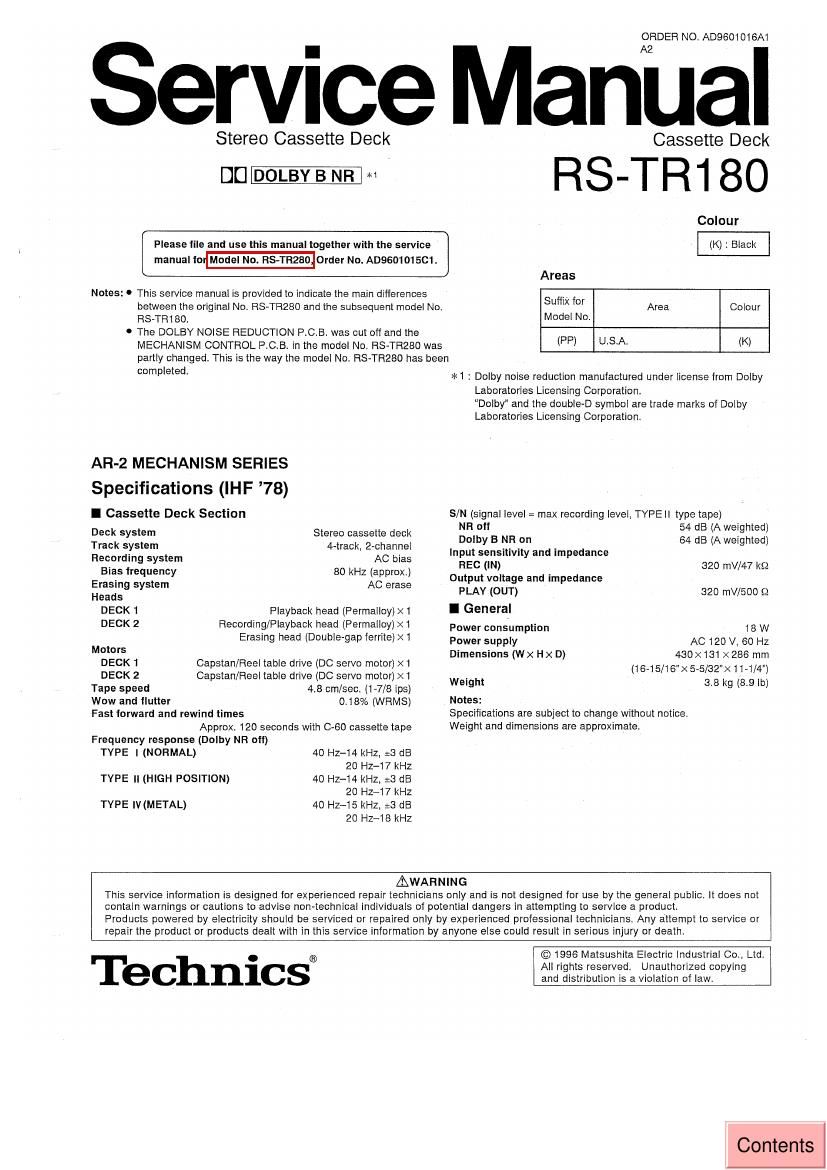
Technics RSTR 180 Service Manual
This is the 12 pages manual for Technics RSTR 180 Service Manual.
Read or download the pdf for free. If you want to contribute, please upload pdfs to audioservicemanuals.wetransfer.com.
Extracted text from Technics RSTR 180 Service Manual (Ocr-read)
Page 1
ORDER NO. AD9601016A1
Service Manual
Stereo Cassette Deck
DC] DOLB_LB NR *1
Please tile and use this manual together with the sen/ice
manual to Model No. RS-TRZBO Order No. AD960101SC1.
Notes: 0 This service manual is provided to indicate the main ditferences
between the original No. RS»TR280 and the subsequent model No.
HS-TRtBO.
0 The DOLBY NOISE REDUCTION PCB. was cut oft and the
MECHANISM CONTROL P.C.B. In the model No. FIS-TRZBO was
Cassette Deck
RS-TRt 80
Colour
(K) : Black
Areas
Suffix ft" Area Colour
Model No.
(PP) U.S.A. (K)
partly changed. This is the way the model No. RS-TRZSD has been
completed,
AR-2 MECHANISM SERIES
Specifications (IHF 78)
I Cassette Deck Section
Deck system
Track system
Stereo cassette deck
4~track, 2-channel
Recording system AC bias
Bias frequency 80 kHz (approx)
Erasing system AC erase
Heads
DECK t Playback head (Permalloy) X1
DECK 2 Recording/Playback head (Permalloy) >
Motors
DECK 1 Capstan/Fleel table drive (DC servo motor) >
Wow and flutter
Fast lorward and rewind times
Approx. 120 seconds with 0-60 cassette tape
Frequency response (Dolby NR otl)
TYPE I (NORMAL)
0.1 8% (WRMS)
40 HZ-t4 kHZ, :3 dB
20 HZ-17 kHz
40 HZ-t4 kHz. :3 dB
20 Hz-17 kHz
40 Hz-t5 kHz. :3 dB
20 HZ~18 kHz
TYPE ll (HIGH POSITION)
TYPE IV (METAL)
*t : Dolby noise reduction manufactured under license from Dolby
Laboratories Licensing Corporation
Dole and the double-D symbol are trade marks of Dolby
Laboratories Licensing Corporation
S/N (signal level: max recording level. TYPEll type tape)
NR oil 54 dB (A weighted)
Dolby B NR on 64 dB (A weighted)
Input sensitivity and impedance
REC (IN) 320 mV/47 k9
Output voltage and impedance
PLAY (OUT) 320 mV/SOD Q
I General
Power consumption 18 W
Power supply AC 120 V. 60 Hz
Dimensions (Wx Hx D) 430x131x286 mrn
(18-15/16"X 5-5/32"Xt1-1/4")
Weight 5.8 kg (8.9 lb)
Notes:
Specifications are subject to change without notice.
Weight and dimensions are approximate.
AWAHNING
This service information is designed for experienced repair technicians only and is not designed for use by the general public. It does not
contain warnings or cautions to advise non-technical individuals of potential dangers in attempting to service a product.
Products powered by electricity should be serviced or repaired only by experienced professional technicians. Any attempt to servtce or
repair the product or products dealt with in this service information by anyone else could result in serious injury or death.
Technics®
© 1996 Matsushlta Electric Industrial Co. Ltd.
All rights reserved. Unauthorized copying
and distribution is a violation of law.
Contents
Page 2
RS-TR1 80
I Schematic Diagram
Page
MAIN CIRCUIT ................. .......... 3.4
E] MECHANISM CONTROL CIRCUIT (DECK 2) ............. .. .. s~7
MECHANISM CIRCUIT (DECK 2). . e
E] FL CIRCUIT. ............. . ....... .. a
E POWER SWITCH CIRCUIT ................... . ...................... ............. a
MECHANISM CIRCUIT (DECK 1) .................. ..................... a
MECHANISM CONTROL CIRCUIT (DECK 1) ................... 5, a
O This schematic diagram may be modified at any time with the development of new technology.
20:72.1 : Power switch (STAND BY (DION)
0 S707 : DECK 1 cassette holder open switch (2 OPEN)
0 S708 : Dolby noisereduction switch (DOLBY NR)
0 S709 : Reverse-mode select switch (REVERSE MODE) /
0 S710 : Synchro-start switch (SYNCHRO START)
0 S711 : Tape-to-tape recording-speed switch (SPEED)
0 S714 : Stop switch (I)
9 $715 : Forward~side playback switch (>)
0 S716 : Reverse-side playback switch (fl)
0 S717 : Fast fonNard switch (>>)
0 S718 : Rewind switch (44)
0 S719 : DECK 2 cassette holder open switch (5 OPEN)
C 5720 : Record pause switch (0 REC PAUSE)
O 5721 : Tape deck select switch (DECK 1/2)
0 S723 : Counter reset (COUNTER RESET)
0 5951 : DECK 1 mode detect switch
I 5952 : DECK 1 half detect switch
I 3953 : DECK t CrOz tape detect switch
I 5971 : DECK 2 mode detect switch
0 5972 : DECK 2 half detect switch
0 $973 : DECK 2 CrOz tape detect switch
0 5974 : DECK 2 reverse side record prevention tab detect switch
I 5975 : DECK 2 torward side record prevention tab detect switch
0 5976 : DECK 2 METAL tape detect switch
I Indicated voltage values are the standard values for the unit measured by the DC electronic Circuit tester (high-impedance) with the chassis
taken as standard. Therefore. there may exist some errors in the voltage values. depending on the internal impedance of the DC circuit tester.
No mark : Playback ( ) : Recording
I Important safety notice:
Components identified by A mark have special characteristics important for satety.
Furthermore, special parts which have purposes of tire-retardant (resistors). high-quality sound (capacitors). low-noise (resistors). etc. are
used. When replacmg any of components. be sure to use only manufacturers specified pans shown in the parts list.
0 Caution!
IC and LSI are sensitive to static electricity.
Secondary trouble can be prevented by taking care during repair.
Cover the parts boxes made of plastics with aluminum foil.
Ground the soldering iron.
Put a conductive mat on the work table.
Do not touch the legs of IC or LSI with the fingers directly.
O Voltage and signal line
-o- : Positive voltage line
rune-nu- : Negative voltage line
I : Playback signal Line
l:> : Recording signal Line