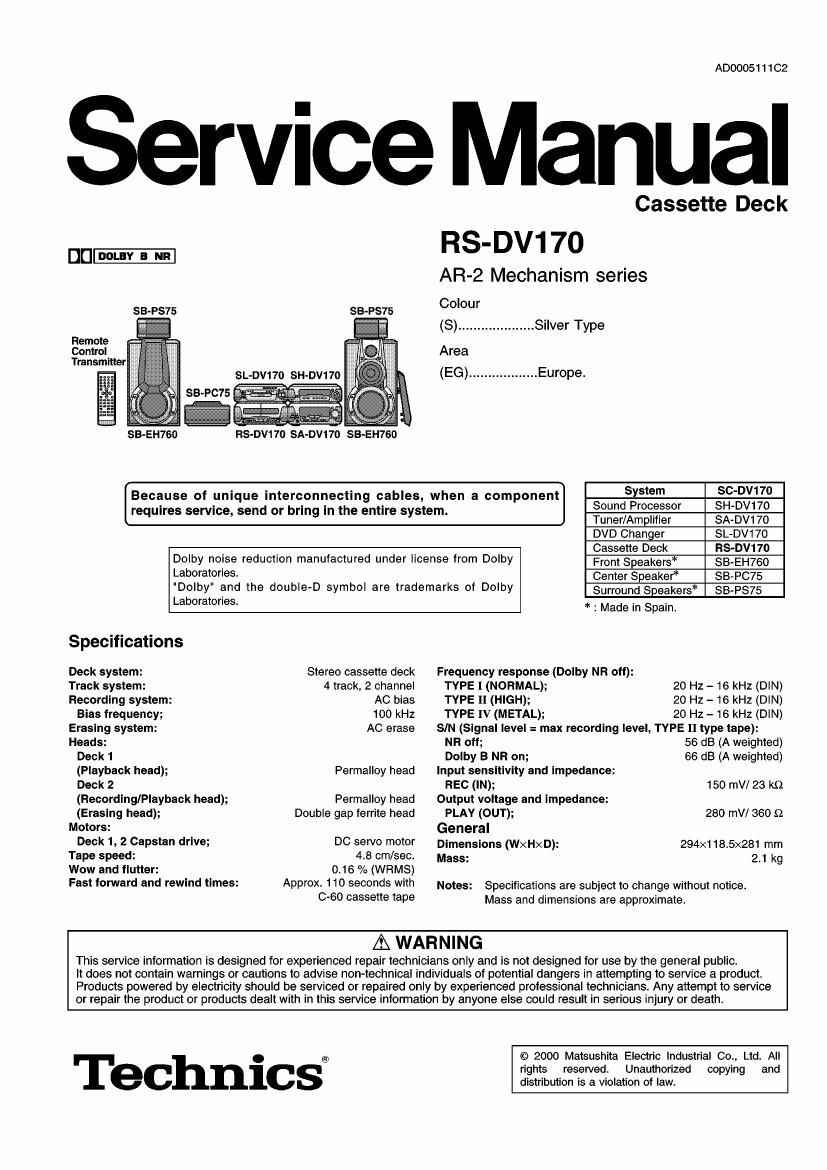
Technics RSDV 170 Service Manual
This is the 33 pages manual for Technics RSDV 170 Service Manual.
Read or download the pdf for free. If you want to contribute, please upload pdfs to audioservicemanuals.wetransfer.com.
Extracted text from Technics RSDV 170 Service Manual (Ocr-read)
Page 1
ADOOOS1 1 102
Service Manual
Cassette Deck
DI] DOLIY a ran
RS-DV17O
AR-2 Mechanism series
SB-PS75 Colour
(8) .................... Silver Type
Area
(EG) .................. Europe.
SB-EH760 Hs-Dvwo SA-Dv17o SB-EH760
Because of unique interconnecting cables, when a component] 8 ngstem 83:3),1177:
re uires service send or brin in the entire 5 stem. °" r°°355°r '
q g y Tuner/Amplifier SA-DV170
DVD Changer SL-DV17O
Cassette Deck RS-DV17O
Dolby noise reduction manufactured under license from Dolby FrontSpeakers* SB-EH760
Laboratories. Center Speaker SB-PC75
"Dolby" and the double-D symbol are trademarks of Dolby Surround Speakers 3543375
Laboratories
* : Made in Spain.
Specifications
Deck system: Stereo cassette deck Frequency response (Dolby NR off):
Track system: 4 track, 2 channel TYPE I (NORMAL);
Recording system:
Bias frequency;
Erasing system:
ACbias 'rvpemmen);
100 kHz TYPE 1v (METAL):
20 Hz - 16 kHz (DIN)
AC erase SIN (Signal level = max recording level, TYPE I] type tape):
Heads: NFt off; 56 dB (A weighted)
Deck 1 Dolby B NR on; 66 dB (A weighted)
(Playback head); Permalloy head Input sensitivity and Impedance:
Deck 2 REC (IN); 150 mV/ 23 k9
(Recording/Playback head); Permalloy head Output voltage and impedance:
(Erasing head);
Double gap ferrite head PLAY (OUT);
280 mV/ 360 Q
Motors: General
Deck 1, 2 Capstan drlve; DC servo motor Dimensions (WxHxD): 294x118.5><281 mm
Tape speed: 4.8 cm/sec. Mass: 2,1 kg
Wow and flutter: 0,16 % (WRMS)
Fast forward and rewind times: Approx, 110 seconds with Notes: Specifications are subject to change without notice.
0'60 cassette tape Mass and dimensions are approximate.
A WAR N | NG
This service information is designed for experienced repair technicians only and is not designed for use by the general public.
it does not contain warnings or cautions to advise non-technical individuals of potential dangers in attempting to service a product.
Products powered by electricity should be serviced or repaired only by experienced prolessional technicians. Any attempt to service
or repair the product or products dealt with in this service intormation by anyone else could result in serious injury or death.
Technicsi
© 2000 Matsushita Electric Industrial Co., Ltd. All
rights reserved. Unauthorized copying and
distribution is a violation of law.
Page 2
CONTENTS
Page
1 Note- ------- 2
2 Location of Controls --------------------------------------------------------------- 2
3 Operation Checks and Component Replacement Proceduress
3.1. Checking for the main P.C.B. ----------------------------------------- 3
3.2. Checking for the operation P.C.B. ----------------------------------- 3
3.3. Replacement for the motor ass 5m, capstan belt and
winding belt ------------------------------------------------------------------- 4
3.4. Replacement for the components pans on the mechanism
P.C.B. --------------------------------------------------------------------------- 6
35. Replacement for the pinch roller ass 5E and head block--7
3.6. Replacement for the cassette lid ass Efl
3.7. Replacement for the cassette holder--
4 To Supply Power Source -------------------------------------------------------- 9
5 Service Mode Function of Cassette Mechanism -------------------- 9
5.1. Cassette tape to be prepared
5.2. Selecting service mode
5.3. Deck 1 mechanism check
5.4. Deck 2 mechanism check --------------------------------------------- 10
5.5. Exiting service mode ---------------------------------------------------- 1o
6 Schematic Diagram Notes
7 Schematic Diagram-
8 Printed Circuit Board Diagram
9 Type Illustration ot le, Transistors and Diodes ------------------ 20
1 Note
Refer to the service manual for Model No. SA-DV170 (Order No. AD000511262) for information on Accessories
Packaging.
2 Location of Controls
Page
10 Wiring Connection Diagram -------------------------------------------------- 20
11 Terminal Function of Ics ...................................................... 21
11-1- |C701 (M38503M2406F):Micro Computer ---------------------- 21
12 Block Diagram ---------------------------------------------------------------------- 22
13 Measurements and Adjustments
13.1. Measurement condition
13.2. Measurement instrument and special tool ..................... 24
13.3. Head azimuth adjustment (Deck 1/2) ---------------------------- 24
13.4. Tape speed adiustment(Deck 112) ................................ 24
13.5. Playback gain adiustment (Deck 1/2)
13.6. Erase current confirmation (Deck 2)
13.7. Playback frequency response check (Deck 1/2)
13.8. Recording/playback frequency response and gain check
(Deck 2) ---------------------------------------------------------------------- 25
13.9. Adiustment point and test point ------------------------------------- 26
14 Checking Procedure for Self-operation ct Cassette
Mechanism Ass 5i! ---------------------------------------------------------------- 27
14.1. Operation Check Providing with cassette Tape ............. 27
14.2. Operation Check Not Provided with Cassette Tape ------- 27
15 Replacement Parts List
16 Cabinet Parts Location
17 Mechanism Parts Location-
and
($5) Deck 1 cassette holder open button (A OPEN)
® Deck 1 cassette holder
(it) Fast forward/rewind buttons (44, >>J
@ Deck 2 cassette holder
® Deck 2 cassette holder open button (A OPEN)
@ Counter reset, display buttons
(COUNTER, RESET, DISPLAY)
® Deck 1/deck 2 select button (DECK 1/2)
® Playback buttons and indicators (<1, l>)
The colour of the indicators depends on the operation taking
place.
If stopped, fast-forwarding or rewinding: orange
If playing or recording: green
While carrying out TPS or recording is on standby: flashes
green
® Stop button (I)
@ Dolby noise reduction button (DOLBY NR)
@ Reverse mode button (REV MODE)
@ Tape edit button (TAPE EDIT)
® Record pause button (0 REC PAUSE)