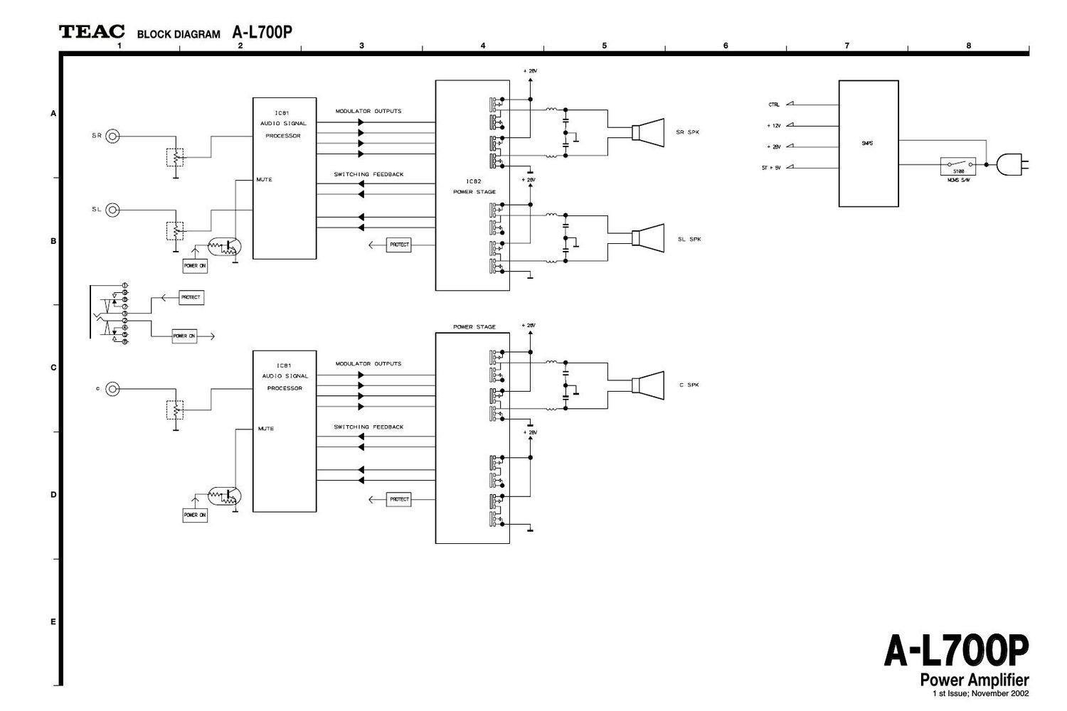
Teac A L700 P Schematic
This is the 4 pages manual for Teac A L700 P Schematic.
Read or download the pdf for free. If you want to contribute, please upload pdfs to audioservicemanuals.wetransfer.com.
Extracted text from Teac A L700 P Schematic (Ocr-read)
Page 1
8 6 7 4 5 2 3 1 E D C B A Power Amplifier A A- -L L7 70 00 0P P 1 st Issue; November 2002 WIRING DIAGRAM A-L700P
Page 2
8 6 7 4 5 2 3 1 E D C B A SCHEMATIC DIAGRAM A-L700P MAIN PCB, DIGITAL AMP PCB Power Amplifier A A- -L L7 70 00 0P P 1 st Issue; November 2002 DIGITAL AMP PCB MAIN PCB-5 MAIN PCB-4 MAIN PCB-3MAIN PCB-2 MAIN PCB-1DIGITAL AMP PCB NOTES:1. Resistor values are in ohms (k=kilo-ohms, M=megohms). 2. Capacitor values are in microfarads (p=picofarads). 3. £Parts marked with this sign are safety critical components. They must always be replaced with identical components-refer to the appropriate parts list and ensure exact replacement.