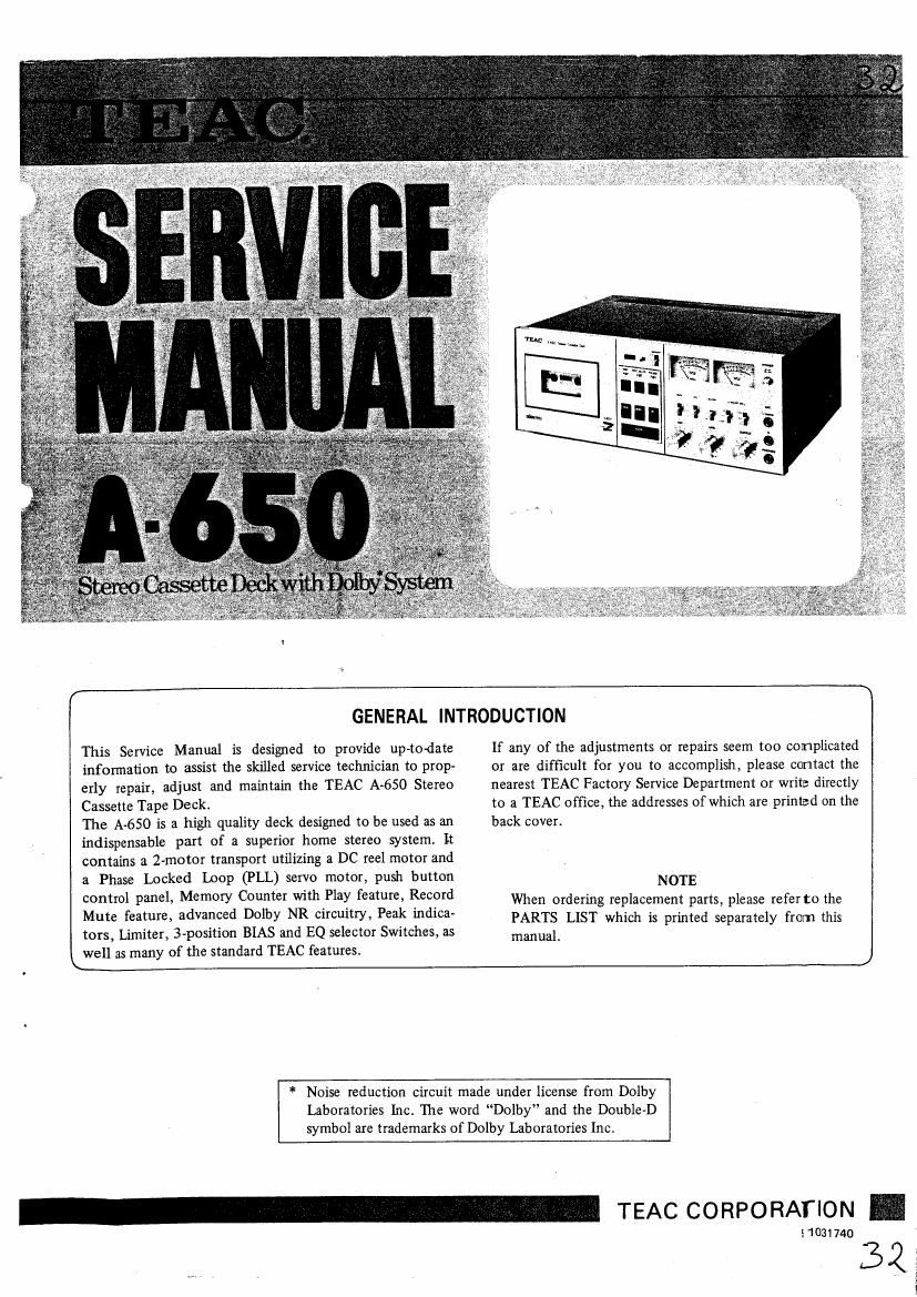
Teac A 650 Service Manual
This is the 63 pages manual for Teac A 650 Service Manual.
Read or download the pdf for free. If you want to contribute, please upload pdfs to audioservicemanuals.wetransfer.com.
Extracted text from Teac A 650 Service Manual (Ocr-read)
Page 1
This Service Manual is designed to provide up-to-date
information to assist the skilled sen/ice technician to prop-
erly repair, adjust and maintain the TEAC A-650 Stereo
Cassette Tape Deck.
The A-650 is a high quality deck designed to be used as an
indispensable part of a superior home stereo system. It
contains a 2-motor transport utilizing a DC reel motor and
a Phase Locked Loop (PLL) servo motor, push button
control panel, Memory Counter with Play feature, Record
Mute feature, advanced Dolby NR circuitry, Peak indica-
tors, Limiter, 3-position BIAS and EQ selector Switches, as
well as many of the standard TEAC features.
GENERAL INTRODUCTION
If any of the adjustments or repairs seem too complicated
or are difficult for you to accomplish, please contact the
nearest TEAC Factory Service Department or write directly
to a TEAC office, the addresses of which are printed on the
back cover.
NOTE
When ordering replacement parts, please refer to the
PARTS LIST which is printed separately from this
manual
* Noise reduction circuit made under license from Dolby
Laboratories Inc. The word Dolby" and the Double-D
symbol are trademarks of Dolby Laboratories Inc.
51031740
_ TEAC CORPORATION -
32:
%
Page 2
Test Equipment Required ................ 3
Specifications & Service Data .............. 4
Parts Location ........................ 6
Partial Disassembly of Main Parts ............ 7
4-1. Case/ Front Panel .............. 7
4-2. Tape Transport Chassis Removal . . . . 7
4-3. Partial Rotation of Front Chassis . . . . 7
4-4. Head ...................... 8
4-5. Pinch Roller ................. 8
4-6 ' Cassette Holder ............... 8
4-7. Capstan Motor ................ 9
4-8. Capstan Drive Assy/ Drive Belt ..... 9
4.9. Reel Motor .................. 10
4-10. Brake Plate Assy .............. 10
4-11. Reel Tables .................. 11
4-12. Idler Assy ................... 11
Mechanical Checks and Adjustments ......... 12
5A1. Take-up Torque ............... 12
5-2. Fast Forward & Rewind Torque . . . i 12
5.3. Pinch Roller Pressure ............ 13
5 .4, Brake Tension ................ 13
5.5, Tape Speed/Wow and Flutter ...... 14
5-5-1. Tape Speed .................. 14
5-5-2, Wow and Flutter .............. 14
5.6. Flywheel Bearing Adjustment ...... 15
5-7. CASSETTE IN Switch Position
Adjustment .................. 16
5-8. RECORD SAFETY Switch
Position Adjustment ............ 16
5.9. Cassette Holder Motion Checks ..... 16
5-10. Oil Retaining Washer Clearance
Check ...................... 16
5-11. Eject Lock Lever Adjustment ...... 17
5-12. Pushbmton Control Checks ....... 18
5-13. Auto-End Stop Facility Check ..... 19
5-14. Memory Device Function Checks. . . . 19
Electrical Checks and Adjustments ........... 19
6-1. Adjustment Location ........... 20
TABLE OF CONTENTS
6-2. Playback Performance ........... 21
6-2-1. Record/Playback Head Azimuth
Adjustments ................. 21
6-2-2. Specified Output Level Setting . . . . . 22
6-2-3. Frequency Response -P1ayback- ..... 22
6-2-4. Signal to Noise Ratio -Playback- . . . . 23
6-2-5. VUMeteI Calibration -P1ayback- . . . . 23
6-2-6. Headphone Output Level Checks . . . . 23
6-3. Monitor Performance ........... 24
6-3-1. Minimum Input Level Checks ...... 24
6-3-2. Specified LINE Control Setting ..... 24
6-3-3. VU Meter Calibration -Record- ..... 24
6-3-4. LED Peak Level Indicator
Calibration .................. 24
6-3-5. DOLBY NR COPY-OUT-FM
Switch Function Check .......... 25
6-4. Recording Performance .......... 25
6-4-1. Bias Trap Adjustments ........... 25
6-4-2. Record Bias Setting ............. 26
6-4-3. Record Level Setting ............ 27
6-4-4. Distortion Checks .............. 27
6-4-5. Frequency Response 40verall- . . . . . . 28
6-4-6. Signal to Noise Ratio - Overall- . , . . 28
6-4-7. Dolby NR Effect Measurement . . . . . 29
6-4-8. Peak Limiter Efficiency Checks r . . . . 29
6-4-9 Erase Efficiency ............... 30
6-4-10. Channel Separation ............. 31
6-4-11. Adjacent Track Crosstalk
Measurement ................. 32
7. Block Diagram ........................ 33
8. Level Diagram ........................ 34
9. Trouble-Shooting ...................... 35
TEAC Test Tape ....................... 5
Lubrication .......................... 1 1
Torque Measurement using the Cassette
Torque Meter ......................... 13
Visual Index (for 5-6, 7, 8,11 Sections) . . . .. .. 15
Voltage and Frequency Setting ............. 17
Page 12
5. MECHANICAL CHECKS AND ADJUSTMENTS
NOTE
All the mechanical checks and adjustments should be done
with the external Cases removed. (See Section 4-1).
5-1. TAKE-UP TORQUE
Specification: 40 ~ 70 gcm (0.6 ~ 1.0 02-inch)
1.
5".
Remove the Cassette Holder. See 4-6 section on page 8.
Switch on POWER.
Set the Cassette Reel Adapter (22 mm Dia.), connected
to the spring scale (0 ~ 70 g, or 0 ~ 2.5 02.) by the
string as shown in Fig. 5-1 on the Take-up Reel Table.
Place the deck in the PLAY mode.
Allow the rotation of the Reel Table to pull the scale
pointer toward the Adapter with the spring scale
moving in the same direction at nearly the same speed
as the tape would be moved, and obtain the scale
reading. Make reading only when the pointer becomes
stable.
The scale should indicate Force of 36 ~ 64 g (1.3 ~
2.2 02.).
This corresponds to a torque of 40 ~ 70 g-cm (0.6 ~
1.0 02-inch). For the torque calculation, refer to Fig.
5-2.
If the reading is out of specified range, clean the
driving surfaces of the Reel Table Assy, and all other
driving parts relative to the take up torque function
with the TEAC TZ-261B Rubber Cleaner or with pure
alcohol.
If the above Cleaning is ineffective for torque correc-
tion, replace the Reel Table Assy. (See Section 4-11).
5-2. FAST FORWARD & REWlND TORQUE
Specification: 100 N 150 g-cm (1.4 ~ 2.1 02-inch)
NOTE
Take-up Reel Table
Cassette Reel Adapter (22mm Die.)
Supply Reel Table
Fig. 54
Y- 406
Take-up/Fast anard Torque Measurement
r Cassette Reel Adapter
Llcm
For example:
If F = 36 9
T = F x r
= 36 x 1.1
= 40 (g-cml
Consequently the torque is 40 gcm
T = F x r
T = torque (g-crn)
F = force (9)
r = radius (cm)
Fig. 5-2 Torque Calculation Method
Note that the Fast Forward and Rewind torque
should be measured before the Auto-End Stop Facil-
ity functions.
5-2-1. FAST FORWARD TORQUE
If the indication is out of specified range, clean the
1. Repeat step 1 and 2 in 5-1 section. driving surfaces of the Reel Table Assy and all other
2. Set the Cassette Reel Adapter (22 mm Dia.), connected driving parts relative to the fast forward torque func-
to the spring scale (0 ~ 200 g, or 0 ~ 7.0 oz.) by the tion with the TEAC TZ-26lB Rubber Cleaner or with
string as shown in Fig. 5-1 , on the Take-up Reel Table. pure alcohol.
3. Place the deck in the Fast Forward mode.
4. Allow the rotation of the Reel Table to pull the scale 5-2-2. REWIND TIJRIIUE
pointer toward the Adapter, and obtain the scale 1. Repeat the FAST FORWARD TORQUE procedure,
reading. Do not read until the pointer becomes stable. but use the Supply Reel Table and Rewind mode for
5. The scale should indicate 91 ~ 136 g (3.2 ~ 4.8 02.). measuring the rewind torque.
This corresponds to a torque of 100 ~ 150 g-cm (1.4 ~ 2. The specified value is the same as that of the fast for-
12
2.1 oz~inch).
ward torque.