Teac A 6100 Mk2 Service Manual

This is the 69 pages manual for Teac A 6100 Mk2 Service Manual.
Read or download the pdf for free. If you want to contribute, please upload pdfs to audioservicemanuals.wetransfer.com.

Page: 1 / 69
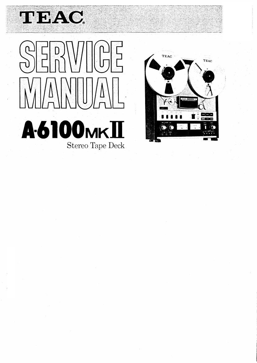
Teac A 6100 Mk2 Service Manual

Extracted text from Teac A 6100 Mk2 Service Manual (Ocr-read)


Page 2

1. GENERAL DESCRIPTION

The TEAC A-6100MKII open reel tape deck is a 1/2 track, 2 channel (stereo) master tape deck
which has 1/2 track record/play capability and also 1/4 track play capability. The A-6100MKII
operates at two selectable speeds, 15 ips and 7-1/2 ips. It can be used with reels of up to 104/2"
diameter. Also, this deck provides a choice of 2 output levels (0.3 V and 0.775 V) which are selec-
table on the rear panel.

- TABLE OF CONTENTS -

1. GENERAL DESCRIPTION ................ 3

2i SPECIFICATIONS AND SERVICE DATA ..... 4

3, TOOLS FOR TESTING AND MAINTENANCE I 6 i

4. PARTIAL DIS-ASSEMBLY ................ 7

5. TAPE TRANSPORT PARTS LOCATION ...... 9
- Rear View 7

6. HEAD REPLACEMENT AND ALIGNMENT . . . 10 ' E
- Mechanical -

7. MEASUREMENT AND ADJUSTMENT ....... 12 g
- Mechanical w

8. MEASUREMENT AND ADJUSTMENT ....... 16
- Electrical 7

9. SIMPLIFIED SCHEMATIC AND LEVEL

DIAGRAMS ......................... 23
IO. SERVICING AND MAINTENANCE ......... 24
11. THEORY OF OPERATION ............... 25

Page 30

) F. FWD AND REW MODES
:fer to Fig. 8

+4v

4 R735
07,3 mli
» n73}

mm +24v
_ 3" R757 0
l 072A ® 95
woe
. was
F8 Ems ®
{9/ _ Fm m4]; arrrwn)
9707-? 7.; me new 5132 5'3
g g cmcurr AL
BTW-10718 am Maren
[33 ® 5 50L STARYWG VOLTAGE
. 0:1sz , comer menu
[0/ © R751 0122,0123 @r- as.
6 D73: 024v
firm 9'2
mse 5
0725

x: (Raw)

+2av ream

i 9; use MODE sw

Y- lZGA

Fig. 8 F. FWD. REW Mode

hen the y» (Fast Forward) key is pressed, the Play Flip
lop and REW Flip Flop will receive a reset signal. At the
me time, the F FWD Flip Flop will be set and its Q out-
ur will become a Low level.

he base current along route 1 will cause 0724 in go ON
nd current flow along route 3 will energize the F. FWD
:lay, K2. Relay K2 will supply the necessary operating
oltage to the reel motor during take up.

iurrent along route 4 will be sent to the reel motor starting
oltage control circuit. Refer to 2-2 (2).

Current along another path on route 2 will turn ON 0722
and Q723 and will energize the Brake Solenoid. The F.
FWD and REW circuits are completely symmetrical. There-
fore, when the 44(REW) key is pressed the same process
occurs as in F. FWD operation and the Brake Solenoid,
Relay K3 and Relay K4 will be energized.

During F, FWD or REW mode, even if the REC MODE
svw'tches are turned ON, the current along routes 5 and 6
will make point A a Low level. Because of this, Q713 will
be OFF, Q714 will be ON and the REC Flip Flop will be
held in reset condition.

5) F. FWD (REW)--> Play

During F. FWD (REW) mode each circuit section will go to the condition as stated below.

am

my
R705 R
- 0719

woman
0715mm

Fig. 9 F. FWD (REW) -> Play

LAY Flip Flop Q output - High, 0719, K1 , Q720, Q72l
1nd Capstan Solenoid H OFF. F. FWD (REW) Flip Flop Q
>utput- Low 0722, Q723 and Brake Solenoid ON Q715
vase Low Q_715- OFF, trigger tomonostable multivibrator
, High Q High, Q718 - OFF. During F. FWD (REW)
operation if the y (Play) key 15 _,pressed the F FWD (REW)
Flip Flop will be reset and its Q output will be High level.

Because of this, the base current is stopped and 0722 goes
OFF.

Then, Q723 goes OFF and also the Brake Solenoid is de-
energized. (Although not shown in Fig. 9, the F. FWD or
REW Relay is also deenergized and the Power supplied to
the reel motors is cut-off).

31