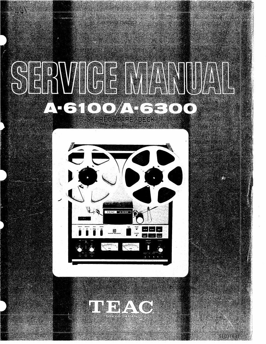
Teac A 6100 A 6300 Service Manual

This is the 112 pages manual for Teac A 6100 A 6300 Service Manual.
Read or download the pdf for free. If you want to contribute, please upload pdfs to audioservicemanuals.wetransfer.com.

Page: 1 / 112
Teac A 6100 A 6300 Service Manual

Extracted text from Teac A 6100 A 6300 Service Manual (Ocr-read)


Page 2

. . o

w m \1 O\ m b w N H
.

P H H H H H H H H
oowoan-waI-Io

¢=CJBJ115BJT13

GENERAL DESCRIPTION ............................................... l
SPECIFICATIONS .................................................. 2,3
TOOLS FOR TESTING AND MAINTENANCE ................................. 4
TEAC TEST TAPE -YTT SERIES- ....................................... 5
TAPE TRANSPORT PARTS LOCATION ....................................... 6
PARTIAL DISASSEMBLY ............................................... 7
LINE VOLTAGE AND FREQUENCY CONVERSION ............................. ll
HEAD ALIGNMENT ..........................;........................ 12
MEASUREMENT AND ADJUSTMENT -MECHANICAL- ........................... l4
A-6lOO ELECTRICAL ADJUSTMENT -GENERAL NOTICE- ..................... l9
MEASUREMENT AND ADJUSTMENT -ELECTRICAL- ......................... 20
A-6300 ELECTRICAL ADJUSTMENT -GENERAL NOTICE- ................¢..... 31
MEASUREMENT AND ADJUSTMENT -ELECTRICAL- .......................... 32
SERVICING AND MAINTENANCE ....................r.................. 42
LIST OF LINE VOLTAGE AND FREQUENCY (Hz) USED AROUND THE WORLD...... 44
TEAC DECIBEL TABLE ............................................... 45
TROUBLESHOOTING ................................................46,47

. LEVEL DIAGRAMS 49,50

NOTE

When placing an order for parts, please refer to the PARTS LIST
and PRICE LIST FOR PARTS which are printed separately from this
manual.

1. File the PARTS LIST manual together with this SERVICE MANUAL;
future TECHNICAL INFORMATION SHEETS should also be kept with these.

2. Use the PARTS LIST manual and the PRICE LIST FOR PARTS when
ordering replacement parts from TEAC Corp.

Page 37

PHONE OUTPUT CHECK

1. Place OUTPUT controls at the Specified Level Setting
with a reference input 400 Hz signal at -8 d3.

2. Connect an 89 non-inductive resistor across the headphone output
(PHONES). Connect Test Set across the resistor.

3. Test Set should indicate -24 dB i2 dB.

fl:

flewv -

(N'

Fig. 13-3 Headphone Load Resistors

MINIMUM INPU_T LEVEL SETTING

LINE Input :

1. Connect an AF oscillator to the LINE IN jacks.

2. Place MONITOR switch in SOURCE; EQ switch and BIAS
switch in #1 position; RECORD MODE switches in ON position.

3. Apply a 400 Hz signal at -18 dB to the LINE IN jacks.

4. Turn LINE input controls fully clockwise, adjust VR-30l/304 to obtain
the specified output level of -8 dB at OUTPUT jacks.

MIC Input:
[This is a check only. No adjustments are to be made.]

5. After adjusting VR-301/304, apply a 400 Hz signal at -70 dB to
the MIC IN jacks.

6. Rotate the MIC controls fully clockwise. This should give an out-
put of -8 dB (specified output level) at OUTPUT jacks.

NOTE: Return MIC controls fully counterclockwise (CCW) to prevent
noise insertion during the following steps.

VU METER LEVEL SET

Verify OUTPUT Controls to be at the Specified output level.
1. Place the MONITOR switch to the SOURCE position. METER switch in NORMAL.

2. Apply a 400 Hz signal at -8 dB to LINE IN jacks.
3. Adjust VR-3OZ/305 for O W (i0.5) on the VU meter.

_35_

Page 51

IPAGKING FDR SHIPMENT

Keep this Carton Box and its packing materials. For shipping,
re-pack as shown in the illustration.

\AIIkFIIII\hrT\(

Your TEAC equipment has been manufactured under the strictest
quality control and is covered by warranty under normal operation.
However, warranty terms may vary with the country (area) in which
it was purchased and for different models of equipment.

The warranty terms are fully described on the warranty card.
Please read the card for complete details. Include a copy of

the warranty in the package when you return the equipment to

an Authorized Service Center.