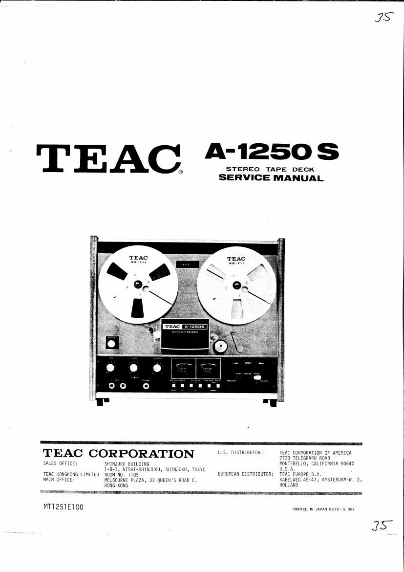
Teac A 1250 S Service Manual
This is the 70 pages manual for Teac A 1250 S Service Manual.
Read or download the pdf for free. If you want to contribute, please upload pdfs to audioservicemanuals.wetransfer.com.
Extracted text from Teac A 1250 S Service Manual (Ocr-read)
Page 1
JS
TEA $1135? 5
®
SERVICE MANUAL
TEAC CORPORATION u.s. DISTRIBUTOR: TEAC CORPORATION OF AMERICA
7733 TELEGRAPH ROAD
SALES OFFICE: SHINJUKU BUILDING MONTEBELLO. CALIFORNIA 90640
1-8-1, NISHI-SHINJUKU, SHIN-JUKU, TOKVO USA
TEAC HONGKONG LIMITED ROOM No HOS EUROPEAN DISTRIBUTOR: TEAC EUROPE BIV.
MAIN OFFICE: MELBOURNE PLAZA, 33 QUEEN'S ROAD CI KABELNEE 45747, AMSTERDAMM. Z,
HONG KONG HOLLAND
MT1251E100
PRINTED IN JAPAN 0872 - S 007
3:,
Page 2
1 GENERAL DESC RIPTIDN
The TEAC A-IZSOS is a semi-professional tape deck for stereophonic
and monophonic recording and playback with automatic reverse. It
offers operating speeds of 7-l/Zips and 3-3/4ips.
The basic design of the A-1250(A-2500) is highly similar to that
of the A-lZSOS, therefore information in this service manual may
be applied to the A-1250(A-2500).
This service manual provides adjustment and alignment procedures,
schematic diagrams and parts replacement information and the proper
procedures for obtaining necessary repair parts.
If adjustments or repair procedures are not clear or seem diffi-
cult to accomplish or should you desire more detailed technical
information, please contact your nearest TEAC dealer, TEAC Cor-
poration or affiliated corporations, address's of which are printed
in this manual.
INDEX
1. GENERAL DESCRIPTION
2. SERVICE DATA
3. EQUIPMENT REQUIRED
4. PARTIAL DISASSEMBLY
5. HEAD ALIGNMENT -MECHANICAL-
6. MEASUREMENT AND ADJUSTMENT -MECHANICAL-
7. SIMPLIFIED DIAGRAMS (WITH VOLTAGE READINGS)
8. MEASUREMENT AND ADJUSTMENT -ELECTRICAL-
9. PREVENTIVE MAINTENANCE
10. TROUBLE SHOOTING
11. PACKING FOR SHIPMENT AND WARRANTY
SCHEMATIC DIAGRAMS
PRINTED CIRCUIT BOARD AND PARTS LIST
EXPLODED VIEW AND PARTS LIST
MANUAL CHANGES
1-1
Page 23
RECORD PERFORMANCE
SPECIFIED INPUT LEVEL SET
1. Apply a 400 Hz signal at -8 dB to the LINE INrjacks.
2. Adjust the LINE control for -8 dB at the OUTPUT jacks.
NOTE: Do not disturb the specified input level position of these
controls until the remaining checks and adjustments are
completed. The difference between the channels must not
exceed i2 dB as indicated on the level meter. If they are
not within limits, check the amplifier gain and the LINE
control settings.
Before making any adjustments on the-record amplifier, be sure that
all tests in the HEAD ALIGNMENT, PLAYBACK and MONITOR PERFORMANCE
sections have been accomplished and that all levels are correct.
Optimum recording performance (bias levels, recording levels and
frequency response) is dependent upon tape characteristics. The
TEAC A-lZSOS is factory set with SCOTCH type 203 (HIGH) and SCOTCH
type 150 (NORMAL) tape.
B IAS TRAP ADJU STMENT
NOTE: The bias trap tank circuit keeps the bias signal from reaching
the record and monitor amplifier and under normal " no signal"
conditions, voltage should not be present at the OUTPUT jacks.
1. Place BIAS switch in HIGH position, MONITOR switch in TAPE position
and RECORD MODE switches "0N". Place tape mode lever at the PAUSE
position. Depress RECORD and ( >) buttons.
2. Connect a VTVM or oscilloscope to the junction of C-308/L-302.
3. Adjust L-302, L-304 (other channel) for minimum reading.
BIAS~OSC
Lana/304
C 308/ an REC HEAD
0303
/ 308
CHECK POINT
M43446
Fig. 8-5 Bias Trap Check Point
8-5