Teac A 107 Service Manual

This is the 52 pages manual for Teac A 107 Service Manual.
Read or download the pdf for free. If you want to contribute, please upload pdfs to audioservicemanuals.wetransfer.com.

Page: 1 / 52
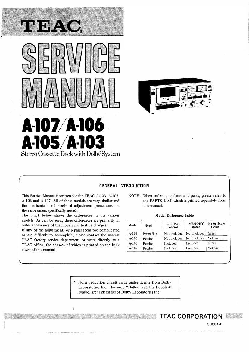
Teac A 107 Service Manual

Extracted text from Teac A 107 Service Manual (Ocr-read)


Page 1

A-l07/A-I06
A-lOS/A-IO3

Stereo Cassette Deck with Dolby System

r \

GENERAL INTRODUCTION

This Service Manual is written for the TEAC A-lO3, A-lOS, NOTE: When ordering replacement parts, please refer to
A-lO6 and A-107., All of these models are very similar and the PARTS LIST which is printed separately from
the mechanical and electrical adjustment procedures are this manual.
the same unless specifically noted.
The chart below shows the differences in the various Model Difference Table
models. As can be seen, these differences are primarily in
outer appearance of the models and feature changes. Model Head 833(31- ngng Mectziostcale
If any of the adjustments or repairs seem too complicated
or are difficult to accomplish, please contact the nearest A403 mm Nmmduded NM mcmdw Glee
TEAC factory service department or write directly to a A405 Ferrite Nmmduded Nmmduded yeuow
TEAC office, the address of which is printed on the back A406 Fem mud dud Gm"
cover of this manual. A-107 Ferrite Included included Yellow

\ J

* Noise reduction circuit made under license from Dolby
Laboratories Inc. The word Dolby and the Double-D
symbol are trademarks of Dolby Laboratories Inc.

TEAC CORPORATION

51032120

Page 2

4-1.
4-2.
4-3.
4-4.
4-5 .
4-6.
4-7.

4-9.
4-10.
4-11.

4-12.

5-1.
5-2.
5-3.
5-4.

5-4-1.
5-4-2.

TABLE OF CONTENTS

Test Equipment Required ............. 3
Specifications & Service Data ........... 4
TEAC Test Tape .................... 4
Parts Location ..................... 6
Partial Disassembly of Main Parts ......... 7
External Parts ..................... 7
Cassette Damper (Damper Cord Stringing) . . . 8
Cassette Holder Assy ................ 8
Reel Tables ....................... 8
Brake Plate Assy ................... 9
Head ........................... 9
Pinch Roller ...................... 9
Motor ........................... 10
Capstan Drive Assy ................. 10
Lubrication ....................... 1 1
Idler ............................ 1 1
Tension Pulley Assy ................. 1 1
Mechanical Checks and Adjustments ...... 12
Take-up Torque .................... 12
Fast Forward & Rewind Torque ......... 12
Pinch Roller Pressure ................. 12
Tape Speed/Wow and Flutter ........... 13
Tape Speed ....................... 13
Wow and Flutter ................... 13

6.
6-1.
6-11.
6-1-2.
6-1 -3.
6-1-4.
6-1-5.
6-1-6.
62.
6-2-1.
6-2-2.
6-2-3.
6-3.
6-3-1.
6-3-2.
6-3-3
6-3-4.
6-3~5.
6-3-6.
6-3-7.
6-3-8.
6-3-9.
6-3-10.
64.

Electrical Checks and Adjustments ........ 14
Playback Performance ................ l4
Record/Playback Head Azimuth Adjustments . 14
Specified Output Level Setting .......... 15
VU Meter Calibration ................ 15
Frequency Response _ Playback - ....... 15
Signal to Noise Ratio - Playback - ....... 16
Headphone Output Level Checks ......... 16
Monitor Performance ................ 16
Minimum Input Level Checks ........... 16
Specified RECORD Control Setting ....... 17
VU Meter Calibration Checks ........... 17
Recording Performance ............... 17
Bias Trap Adjustments ................ 17
Record Bias Setting .................. 18
Record Level Setting ................. 18
Distortion Checks ................... 19
Frequency Response Checks - Overall - . . . 19
Signal to Noise Ratio - Overall - ........ 20
Erase Efficiency .................... 20
Channel Separation .................. 21
Adjacent Track Crosstalk Measurement ..... 22
Dolby NR Effect MeasUrement .......... 22
Adjustment Location ................ 23
Level Diagram ..................... 24
Block Diagram ..................... 26
Voltage and Frequency Setting .......... 27

Page 21

record -L

(l) g 03::2m E

rewind b
(4) _-m u R

_mll L

rewind b plu andcom-ore
nun-u...-
erased A
Sgnol E Erased
(3) 1:11:12?
u-n-I- was
Fig. 6-15 Erase Efficiency Chock Procedure
5-3-8. CHANNEL SEPARATION
Pre nations: mum
Specification: 30 dB (min) P O 3
$0qu .8 MP W
NOTE: To check channel separation (cross talk between 0
channels), a 1 kHz narrow bandpass filter should °
be used. The test signal delivered from an AF oscil- 0 3 AC mums»:

lator should be tuned to the filter used.

Numbers in parentheses correspond to steps in Fig. 6-17.

1. Load a TEAC MTT-SOSB test tape.

2. Apply a 1 kHz test tone at -9 dB (274 mV) into the
left channel.

3. Place the deck in the record mode for about 30 se-
conds. ............................. (1)

4. Rewind the tape to the starting point of recording. (2)

5. Play the tape and measure the output level differences
between the left and right channels .......... (3)

6. A 30 dB difference or more is required.

DECK
mug- mm mm FILTER El
under TEST Wfi-zl- o o

Fig. 1-16 Connection """'
Switch Setting:
INPUT BIAS EQ DOLBY NR
LINE C102 CI02 OUT

Control Setting:
OUTPUT: Specified Setting (See 6-1-2)
(on A-l06/A107 only)

RECORD: Specified Setting (See 6v2-2)

record
(I)

(2)

(3)

- Signal

E Blank '
1-561

Fig. 6-17 Channel Separation Check Prondure

21

Page 24

7. LEVEL DIAGRAM

> NOTE: Models A-103 and A-105 have no OUTPUT Control as shown in this
Simplified Circuit Diagram and these Level Diagrams. Models A-106
and A-107 are similar except they use an OUTPUT Control.

PLAYBACK SECTION .

II N

l W 0

V w "35 w ""5" 3 YIOI
mu

f"- ' m "
-L 2r .
now may " was my W F \ >-
Jm-g mos

- _ -' we:
M as :73: - - m- cm __
I w 10'" ° W m {T --$

J.
M mom
a» l r _______ , @
"w Lil [FEMLL -31? Li. A / Fl; " "m"
:11 '5 ... va v.43 / @flfhém
I , ., J 9
film R302 | A / mu:

v v sacs

2., mv my I!
2. av - LA, 05:
WP
- 4 ESOI L J
T '- x ms: new
9
- M - - 1
. 5502 For A~l06/A-IO7

Iv

TOW ' VIP.

METER

"swag/74:57 """""""" 1

I
E
NOTE: ' REF. Nos. shown in the diagmm relate only i
to the left channel :
- 0 :13 = 0.7 75 v :
' OUTPUT control (R184) for A-106/A-107 :
are positioned at Specified Output Level. :
. Each level given in the diagram shows values :
during playback with 'M'IT-lSO Test Tape L_::: _____ J
(Dolby tone).

I
I
I
I
I
I
I
I
I
I
I
I
I
I
I
I

24