Tandberg TD 20 ASE Service Manual

This is the 12 pages manual for Tandberg TD 20 ASE Service Manual.
Read or download the pdf for free. If you want to contribute, please upload pdfs to audioservicemanuals.wetransfer.com.

Page: 1 / 12
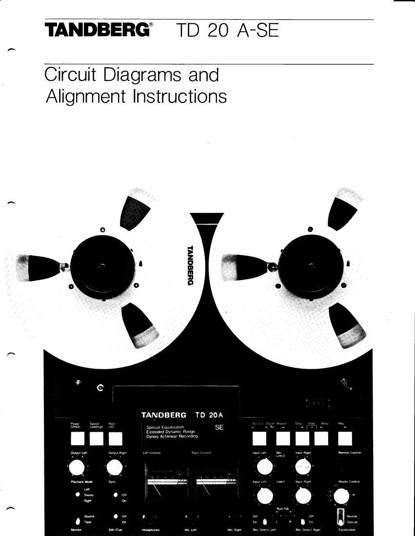
Tandberg TD 20 ASE Service Manual

Extracted text from Tandberg TD 20 ASE Service Manual (Ocr-read)


Page 1

Electrical adjustments TD 20A-SE Make the adjustments in the order in which they are listed here. Many of the adjustments require that previous adjustments have already been correctly made. Clean and degauss the tape path before and after adjustments. lt is assumed that the tape path has already been correctly adjusted as described in the Service Manual for the TD 20A, part No. 714127. Maxell UD XL or equivalent tapes should be used for recording. Necessary equipment - d.c. voltmeter. - 2 high impedance voltmeters (do NOT use universal meters). - Frequency counter. - Audio generator. - Distortion meter. - Wow meter (required for wow test only). - Test tapes: No. 2 - Azimuth adjustment playback head, 15,000 Hz,7/z ips. No. 3 - Playback cule, DIN 19H,7%ips. No. 4 - Playback level adjustment, 4OO Hz, 7% ips. No. 11 - Speed check, 1000 Hz, 7%ips. Bias Adjustment (front panel) Before adjustment, make sure that the Bias Adjust- ment potentiometers on the front panel are in the mid-position. Checking the oscillator frequency Connect a frequency counter directly to the record head. Adjust the frequency to 123.5 kHz in stereo recording with C313 on the logic board. Then check in mono, left and right, that the frequency are within !.2 kHz. lf outside the tolerance, adjust C303, DUMMY LOAD ADJ. on the audio board. Then check the frequency in stereo and mono left and right. Checking the Bias Adjustment (front panel) Connect an audio-generator to LINE 1. Start stereo recording at7%ips speed of a22kHz signal 30 dB below normal recording level (0 dB). Set the Monitor switch to Tape. Check that the output level measured with a.c. voltmeters on the LINE OUT are within approximately + 3 dB to - 5 dB when turning the Bias Adjustment potentiometers. Adjustment of EOT/BOT sensor To be performed without tape. Measure with a d.c. voltmeter on pin 3, contact 412 on the logic board. Adjust R422 (on the logic board) to 1.2 V reading on the voltmeter. A\ ,^ 4 Test Adjustment No. or check Test tape Set the No. deck to Measuringtnstrument Measure at Adjust Correclreadino Speed Comments 1.1 Azimuth,playback head 2 Playback.c^,,-r:-^.:^-.LquoI4oLrvrr.Normal. voltmeters LINE OUT Azimuthscrew,playbackhead Maximumoutput, see comments 7% ios Maximum output or best compromtse. 1.2 PlaybackcuryeDIN 19H 3 Playback.Equal ization: Nomal. a.c.voltmeters LINE OUT PlaybackE.Q. adj. R501 /R601 +2dBat 18 kHz 7% ips. Playback curue, DIN '19H, The tape contains the following frequencies: 1000 Hz (reference) 18 kHz, 15 kHz, 10 kHz, 4 kHz, 125 Hz, 40 Hz '1000 Hz (ref.). Ad.iust R501/R601 to + 2 dB at 18 kHz. 1.3 PlaybacktNet 4 Playback.Equalization:Normal or Somial a.c.voltmeters LINE OUT PlaybacklevelR I 69/R269 0.9 volt 7'h ips. 1.4 Speed 11 Playback. Frequencycounter LINE OUT ! o.5'/.995-1005 Hz in 7% ios. Test taoe No. 1 1 * is recorded at 1000 Hz in 7% ips. ' Test tape No. 'l 1 is supplied on a small reel. This test tape should be spliced into a tape on a larger reel ^al

Page 2

TesNo. Adiustmenlor check Measuringinstrument Measure at Set the deck to Monitorswitch io Procedure 2.1 Biaspre-adjustmen voltmeters LINE OUT Record.Speed: 7% ipl Equalization:Normal. Tape Connet an audio-generator to LINE 1. Set the generator to 1Z.b kHz 30 dB below normal r*ordjng level (0 dB). Adjust RlSl and R251 to maximum outour level. Then turn R151 and R251 counter clockwise to - 2 dB from maximum readino. 11 Azimuth,rsord head a.c.voltmeters LINE OUT Record.Speed: 77: ip: Equalization:Normal. Tape Connst an audio-genemtor to LINE t. Start rcording at 7% ips. of a 10O0 Hz signal 30 dB below normal recording level (O dB). Use the voltmeter readings as reference level. Then rmord a 25,000 Hz signal and turn the azimuth screw on the record head to maximum reading or best compromise on the voltmeters. 2.5 Record/playbackcurues voltmeters LINE OUT Record.Speed: 7% ips Equalization:Normal. Tape Connst an audio-generator to LINE 1. Start rmording of a 1000 Hz signal 30 dB below normal recording level (0 dB). Use the voltmeters readings as reference level (0 dB). Then turn the generator to 12.5 kHz and adiust R151 and B25l to 0.5 dB from the reference level. Turn the generator to 25 kHz and adjust R139 and R23g to 0 dB. Check that the output level do not deviate more than J 2 dB from 20 Hz to 25,000 Hz. Record/playbackcuryes voltmetem LINE OUT B ecord.Speed: 15 ips. Equalization:Normal, Tape Use the same recording level as in test 2.3. Use the voltmeters readings as reference level. Check that the output level do not deviate more than 1 3 dB from 20 Hz to 30.000 Hz. Adjust if necessary with PLAYBACK E.O. ADJ. B5O1/8601 and,/or BIAS ADi. R151/ R251. lf re-adjustment is done, check once again that the output lwel in 7% ips, Equalization: Normal do not dwiate more than r 2 dB from 20 Hz to 25,000 Hz. Adiust if necessary with R139/R239. Record/playbackcuryes voltmeters LINE OUT Becord.Speed: 15 ips. Equalization:Special. fape Use the same recording level as in test 2.3. Use the voltmeters readings as reference level. Turn the generator to 30 kHz and adjust R135/8235 to 0 dB. Chek that the outDut level do not dwiate more than i 2 dB from 20 Hz to 30.000 Hz. 2.6 Record/playbackcurues a,c.voltmete6 LINE OUT Record.Speed: 7% ips Equal ization: Speria l. Tape Use the same rffording level as in test 2-3. Use the voltmeters readings as refereance level. Check that the output level do not deviat€ more than i 2 dB from 20 Hz to 25.000 Hz. Source,/Tape a.c.voltmeters LINE OUT Record.Speed: 7% ips Equalization:Normal. Source/Tape Connect an audio-generator 1000 Hz to LINE 1. Adjust in Source with the Input Levels to 0.6 V on the voltmeters on the LINE OUT. Set the deck to stereo recording 3nd set the Monitor switch to Tape. Then adjust R142 and F.242 so that the level reading is 1 dB higher on the voltmeters. 2.6 Programmeteradjustment voltmeters LINE OUT Speed: 7% ips Equalization:Normal. Source Connect an audio-generator 1000 Hz to LINE 1. Set the Monitor switch to Source. Adiust with the Input Levels to 1.5 V reading on the voltmeters. Then adjust the program meters to 0 dB with R158 and R258 (Output Left and Right on maximum). 2.9 DYNEO@leveladjustment Programmeters LINE OUT Speed: 7% ips Equal ization: Normal. Source Connect an audio generator to LINE 1. Set the generator to 1 kHz. Adjust with the input levels to - 3 dB on the program meters. Then set the generator to 1 8 kHz and set the program meters to + 2 dB with the oYNEQ SENSITIVITY ADJ. (on leit side of the chassis). 2.1C Distortion voltmeter/distortionmerer LINE OUT Record.Speed; 7% ips Equalization:Normal Tape Connmt an audio-generator at 1000 Hz or the distortion meter generator to LINE 1. Record to 0.9 V reading on the voltmeters and read the distortion on the LINE OUT Distortion maximum 0.5%. 2.11 Wow and flutter Wow and fluttermeter LINE OUT Record. Tape Connet the wow and flutter meter to LINE 1. Read on the LINE OUT in highest and lowest speed: 3% ips. 7%ips. 15 ips. Wow and ilutter maximum: Weishted RMS OJO% 0.05% 0.m% Peak value DIN 45500 P.4. O.14y' 0.08% 0.06% OSC. FREO. ADJ. IS ON THE LOGIC 8OARO. PLAYBACK EO. ADJ. IS ON THE PLAYBACK AMP. BOARD. LRaaR15r R25t BIAS ADJ, OUMMY LOAD ADJ, ac303 ; PLAYB. R169 L LEVEL B .METERADJ I qrqn R269 -- REC. LEVEL L Raa Rt42 R242 R REC. EQ. ADJ. aaL i|ffl?:i n,?sn?rs --"oi.^ Low HtGH RaR258 METER AOJ, Location of Adjustment points on the Audio Board, solder side