Studer 169 Service Manual 3
This is the 50 pages manual for Studer 169 Service Manual 3.
Read or download the pdf for free. If you want to contribute, please upload pdfs to audioservicemanuals.wetransfer.com.
Extracted text from Studer 169 Service Manual 3 (Ocr-read)
Page 1
ETUEJEE} 1.169.310/311; 320/321; 330/331; 340/341 SECTION 7.6/2
7.6.1 7.6.1
Summenverstérker Summing amplifier
. . R
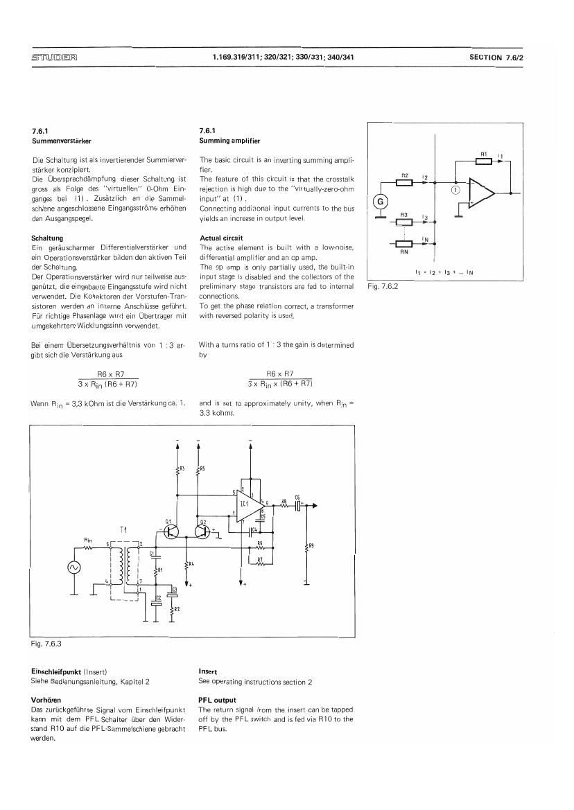
De Schaltung ist als invertierender Summierverr The basm circuit is an inverting summing ampli- -E-l>1-
Starker konzipiert. fisr, M
Die Ubersprechdamptung dieser Schaltuhg ist The feature of this circuit is that the crosstalk 2
gross als Folge des virtuellen" O-Ohm Einr rejection is high due to the virtually~zer0»0hm @ _
ganges bet it). Zusatzlich an die Sammelv input at ll). +
schiene angeschlossene Eingangsstrbme erhéhen Connecting additional input currents to the bus
den Ausgangspegel. yields an increase in output level. " #_, "
thaltung Actual circuit lN
Ein gerauscharmer Ditterentialverstarker und The active element is blult with a lowAnoise. Emu w
ein Operationsverstarker bilden den aktiven Teil differential amplifier and an op amp.
der Schaltung. The op amp is only partially used, the built-in I = I + I +
Der Operationsverstérker wird nur teilweise aus~ input stage is disabled and the collectors of the 1 Z 3 N
genuut, die eingebaute Eingangsstute wird nicht preliminary stage transistors are fed to internal Fig. 7.6.2
verwendet. Die Kollektoren der Vorstufen-Tranr connections.
sistoren werden an interne Anschliisse gefithrt. To get the phase relation correct, a transformer
Far richtige Phasenlage wird ein Ubertrager mit with reversed polaritv is used.
umgekehrtem Wicklungssinn verwendet.
Bei einem Uhersetzungsverhaltnis von 1 : 3 are With a turns ratio oti : 3 the gain is determined
glbt sich die Verstéirkung aus by
H6 >< H7 H6 x R7
3thian6+R7) 3XR1n><(R6+R7)
Wenn Rm = 3,3 kOhm Ist die Verst'arkung ca. i. and is set to approximately unity, when Rin :
3,3 kohms.
; ,
i
It! HS
5
1
Hz
,
in.
+ + A
Fig. 7.63
Einschleifpunkt (insert) Insert
Siehe Eedienungsanleitung. Kepitel 2 See operating instructions section 2
Vorhtiren PFL output:
Das Zurljckgefuhrte Signal vom Einschleifpunkt The return signal from the insert can be tapped
kann mit darn PFL-Schalter fiber den Wider! off by the PFL switch and is fed via FllOto the
stand R10 auf die PFL-Sammelschiene gehracht PFL bus.
werden.
Page 2
STU©EFZ
1.169.310/311 ; 320/321 ; 330/331; 340/341
SECTION 7.6/3
ldentifikationsschalter
Der tdemiflkationsschaiter gestattet ein identifi-
kationssignai mit Leitungspegel zu senden.
Probebetrieb rnit Summen-PFL ist mégiich.
Der Oszillator ist in der NachhaIi-Einheit pia-
ziert und versorgt die Sammelschiene PP3~13
rnit einern Signal von ca. 1 kHz.
Regler
Siehe Beschreibung1.169.550 Kapitel 6
Impedanz-Wandler
Dieser Verstarker besitzt einen gerauscharmen
Eingangstransistor und eine Gegentaktstuie der
K1asse A. 05 wird tiber C11 gesteuert.
Die Gesarntverstérkung ist gieich 1.
7 .62
Begrenzer
Spannungsgeregelter Abschwa'cher und Aufhol-
verstérker
Einem spannungsgeregelten Abschwacher folgt
ein festeingesteilter, geréuscharmer Verstérker,
Das Regeieiernent ist ein FET.
Urn einen tiefen Kiirrfaktor zu erreichen, wird
der Pegel rnit R22, R24 um 4 dB reduziert.
R25 und 06 bilden den geregetten Abschwé-
cher. Der Pegei am Verstérkereingang WIrd aut
-24 dBu konstant gehalten.
Trimmpotentiometer R25 wird auf r0 des FET
abgegiichen.
Die Initialdampfung des gerege1ten Abschwa-
chers betra'gt 0,5 dB. Bei ausgeschaltetem Be-
grenzer wird mit R21, R23 diese Initiaidampr
fung nachgebildet.
[dent switch
AHOWS transmission of an identification signal
to the iine in OB sen/ice.
Rehearsa1 is stiii possibie Via the master PFL.
The osziilator is located in the reverb/foldback
unit and feeds the bus PP3-13 with a signai of
approximateiy 1 kHz.
Fader
See description 1.169.550 section 6
Impedance matching amplifier
Consists of a iowrnoise input transistor and a
push»pu1i output stage in class A.
0515 controlied via C11.
Overali gain is unity.
7.6.2
Limiter
Voltage controlled attenuator and booster am-
plifier
A voltage controiied attenuator is toiiowed by a
fixed gain, iow-noise amplifier. The control eie-
rnent is a PET.
To keep the distortion 10w, the 1eve] is attenu-
ated by 4 dB with R22, 924.
R25 and 06 form the controiled attenuator.
The 1eve| at the input of the amplifier is kept
constant at -24 dBu.
R25 is variable to be adjusted according to ru of
the FET.
in normai lineup the controiled attenuator has
an initiai attenuation of 05 dB, in off-position
an additional attenuator R21, R23 simuiates
this level difference.
-> l
W
Fig. 7.6.4