Spendor s 35 se owners manual

This is the 3 pages manual for spendor s 35 se owners manual.
Read or download the pdf for free. If you want to contribute, please upload pdfs to audioservicemanuals.wetransfer.com.

Page: 1 / 3
spendor s 35 se owners manual

Extracted text from spendor s 35 se owners manual (Ocr-read)


Page 1

spendor 53/5se User M anual Sheet 1 of 3

Loudspeaker positioning and room acoustics
Spendor loudspeakers are carefully engineered to suit a wide variety of listening rooms. Please use the
following guidelines to ensure they are correctly installed for optimum performance.

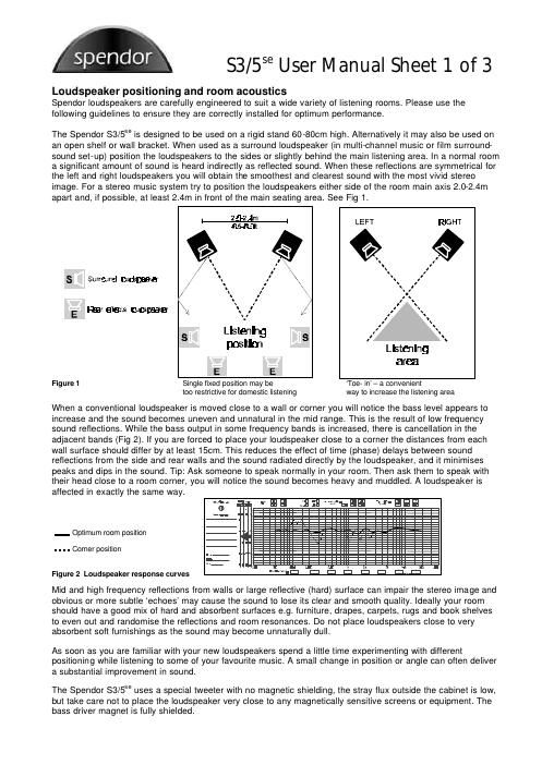
The Spendor 83/5SS is designed to be used on a rigid stand 60-80cm high. Alternatively it may also be used on
an open shelf or wall bracket. When used as a surround loudspeaker (in multi~channel music or film surround-
sound set-up) position the loudspeakers to the sides or slightly behind the main listening area. In a normal room
a significant amount of sound is heard indirectly as reflected sound. When these reflections are symmetrical for
the left and right loudspeakers you will obtain the smoothest and clearest sound with the most vivid stereo
image. For a stereo music system try to position the loudspeakers either side of the room main axis 2.0-2.4m
apart and, if possible, at least 2.4m in front of the main seating area. See Fig 1.

2. ' .
5.5% :Iit LE FT RI GHT
» ,
\ i" _ \ I
. \ I '. ¢
S Surrand Iouwm-ar \ , s "
,I \ i
' \ I ,
\ I 4
X 1' ', \
Rear discs faucslaaakar , . ' X s
. ' . Ir \
, s
S Llsteitnlng S X, \
pos m Listening
area
E E
Figure 1 Single fixed position may be Toe- in - a convenient
too restrictive for domestic listening way to increase the listening area

When a conventional loudspeaker is moved close to a wall or corner you will notice the bass level appears to
increase and the sound becomes uneven and unnatural in the mid range. This is the result of low frequency
sound reflections. While the bass output in some frequency bands is increased, there is cancellation in the
adjacent bands (Fig 2). If you are forced to place your loudspeaker close to a corner the distances from each
wall surface should differ by at least 150m. This reduces the effect of time (phase) delays between sound
reflections from the side and rear walls and the sound radiated directly by the loudspeaker, and it minimises
peaks and dips in the sound. Tip: Ask someone to speak normally in your room. Then ask them to speak with
their head close to a room corner, you will notice the sound becomes heavy and muddled. A loudspeaker is
affected in exactly the same way.

.m .... TEE a-n...-... an! -\.-.Ei=li:|
Era . -- GE :Iizrizi

$

_ Optimum room position

. . . . Corner position

lllll

1 m 5.:

. i:- , n n 1. HI.
'"'-:| El El El El i:| QB

Figure 2 Loudspeaker response curves

Mid and high frequency reflections from walls or large reflective (hard) surface can impair the stereo image and
obvious or more subtle echoes may cause the sound to lose its clear and smooth quality. Ideally your room
should have a good mix of hard and absorbent surfaces e.g. furniture, drapes, carpets, rugs and book shelves
to even out and randomise the reflections and room resonances. Do not place loudspeakers close to very
absorbent soft furnishings as the sound may become unnaturally dull.

As soon as you are familiar with your new loudspeakers spend a little time experimenting with different
positioning while listening to some of your favourite music. A small change in position or angle can often deliver
a substantial improvement in sound.

The Spendor 83/5SS uses a special tweeter with no magnetic shielding, the stray flux outside the cabinet is low,
but take care not to place the loudspeaker very close to any magnetically sensitive screens or equipment. The
bass driver magnet is fully shielded.

Page 2

53/5se User Manual Sheet 2 of 3

Basic connection and quick set-up

All loudspeakers need to be rigidly mounted to ensure a clear and focussed sound. Switch off your amplifier(s).
Check that the supplied terminal links are installed between the HF and LF inputs. For information on bi- wiring
and bi~amping see later. Always connect the -ve (usually black) loudspeaker output terminal of the amplifier to
the corresponding -ve (black) terminal on the loudspeaker. Always connect the we (usually red) loudspeaker
output terminal of the amplifier to the corresponding +ve (red) terminal on the loudspeaker. Always connect the
left channel amplifier output to the left loudspeaker and the right channel amplifier output to the right
loudspeaker. Make the connections as shown below (Fig 3). Turn the volume down and switch on the amplifier.
Pick a source (CD, FM etc.) and advance the volume carefully.

Amplifier left channel output
- +

-» e) (a
I

Figure 3 Loudspeaker Connections - Single Wiring

Left channel loudspeaker
Terminal links in place

Only left channel shown

Bi-wiring
Bi-wiring improves sound quality by separating the current paths for Low (LF) and High (HF) frequencies. Make
the connections as shown below (Fig 4). Store the terminal links safely.


Amplifier left channel output

. +

Left channel loudspeaker

Terminal links removed

Only left channel shown

Figure 4 Loudspeaker Connections for Biwiring

Bi-amping

Biamping allows two independent audio power amplifier of equal or similar quality to be used for LF and HF
signals. The benefits of bi-amping include reduced intermodulation distortion because the low and high
frequency signals are amplified independently, and more power reserve and dynamic range because each
amplifier has less work to do than a corresponding single amplifier. For bi~amping make the connections as
shown below (Fig 5). Terminal links MUST be removed before bi-amping. Store the terminal links safely.

_+@

Hr- HF Amplifier( (Left Channel) LF Amplifier( (Left Channel)


Left Channel Loudspeaker
L.

«age (so

Terminal Links Removed

Only left Chan nel shown

Figure 5 Loudspeaker Connections for Bi-amping